2 EASY
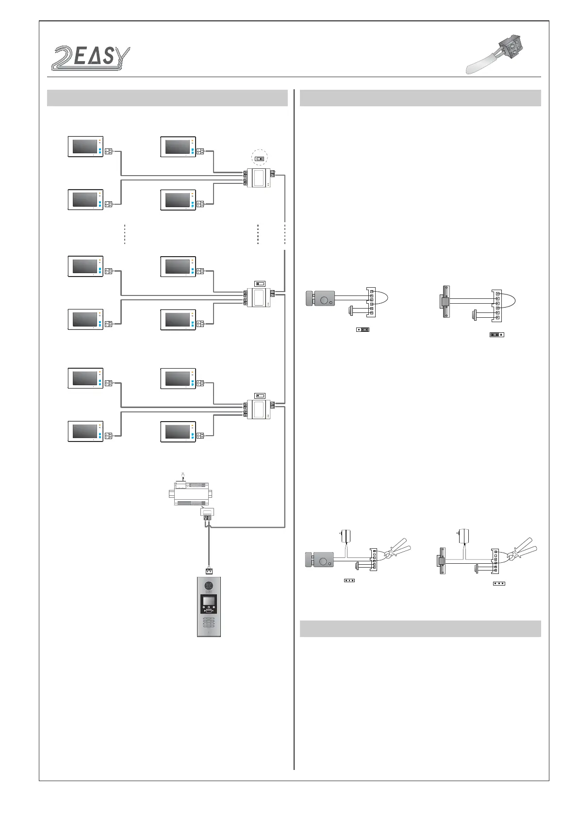
SYSTEM CONNECTION
OFF ON
OFF ON
DBC4A
A B C D
DBC4A
A B C D
Impedance
switch
Impedance
switch
100~240VAC
BUS(IM) BUS(DS)
PC6
AC~
OFF ON
DBC4A
A B C D
Impedance
switch
Code=28
Code=30
Code=29
Code=31
Code=4
Code=6
Code=5
Code=7
Code=0
Code=2
Code=1
Code=3
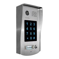
1 2 3
654
7 8 9
#0
*
RF CARD
ELECTRIC LOCK CONNECTION
1) Door Lock Controlled with Internal Power
1. The door lock is limited to 12Vdc, and holding current must be less
than 250mA when using internal power supply mode.
2. The Unlock Mode Parameter must be set to 0 (by default).
3. Jumper set to 1-2 position for power-off-to-unlock safety
type(
Normally closed mode
); set to 2-3 position for power-on-to -un-
lock type(
Normally open mode
).
4. If different unlocking time is needed to be congured, change the
unlock time on door station,detail information refer to DT system tech-
nical guide .
2) Door Lock Controlled with External Power
1. The external power supply must be used according to the lock.
2. The jumper must be taken off before connecting.
3. Setup the
Unlock Mode Parameter
for different lock types
• Power-on-to-unlock type:Unlock Mode=0(by default)
• Power-off-to-unlock type:Unlock Mode=1
4. If different unlocking time is needed to be congured, change the
unlock time on door station,detail information refer to DT system tech-
nical guide .
JP_LK
12V 300mA
Exit button
Jumper position in 2-3
+
-
+12V
LK -
LK+
N.O.
EB-
EB+
1 2 3
Power-on-to-Unlock type:
Power-on-to-Unlock type:
12V 300mA
Jumper position in 1-2
+12V
LK -
LK+
N.O.
EB-
EB+
+
-
1 2 3
Exit button
Power-off-to-Unlock type:
Power-off-to-Unlock type:
+
+
-
-
+12V
LK - (GND)
LK+(COM)
N.O.
EB-
EB+
Take off the Jumper
JP_LK
Cut off the line
1 2 3
Exit button
+12V
LK - (GND)
LK+(COM)
N.O.
EB-
EB+
Take off the Jumper
+
+
-
-
JP_LK
Cut off the line
1 2 3
Exit button
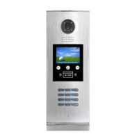
SPECIFICATION
• Power supply: DC24V
• Camera Lens: 1/4 ACS 4T image sensor
• Power consumption: Standby 33mA; Working status 157mA.
• Screen: 3.5 inch TFT
• Resolution: 320(R, G, B)X240 pixels
• Video signal: CCIR/EIA optional
• Wiring: 2 wires, non-polarity
• Dimension: 350(H)×128(W)×46(D)mm
• Note: The diagram take the monitor of DT47M for example.
DMR18S Technical Menu -3-
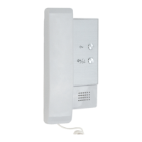
INTRODUCTIONS
Installation Guide