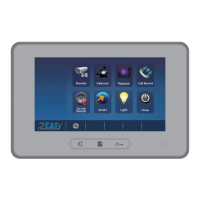
2 EASY
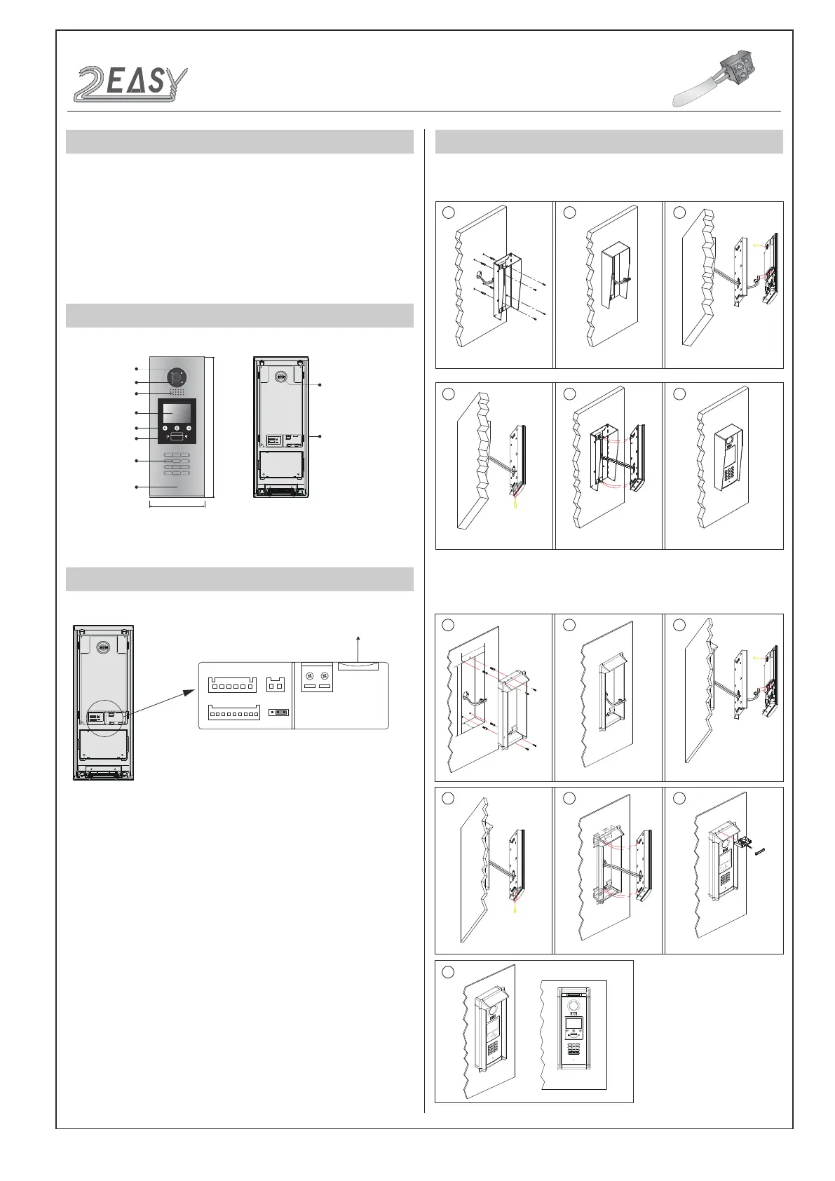
DESCRIPTION MOUNTING
As an upgrade of DMR18, DMR18s has more stable and stronger abil-
ity of communication. It achieves call model of 128 families, expands
capacity of the system. It also adds many special functions such as
select by touching keypad, namelist, voice prompt, etc. , which brings
clients fresh and modernized experience. And for convenience, users
can upgrade UI and Voice through SD card by themselves.
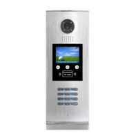
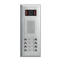
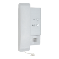
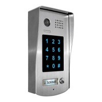
PARTS AND FUNCTIONS
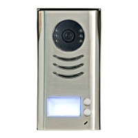
Camera Lens
Night View LED
Speaker
Adjustable Camera
Connectiong Port
350 mm
128 mm
1 2 3
654
7 8 9
#0
*
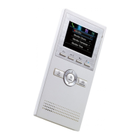
LCD Screen
ID Card Window
Digital Keypad
Microphone
12
3
Touch Key
RF CARD
TERMINAL DESCRIPTION
L1
T/R -
CN-LK
T/R+
J/KMB JP-LK
Bus
SD Card Slot
EB+
EB-
N.O
LK+
LK-
+12V
L2
12
3
12
3
•
+12V:
12VDC power output.
•
LK-(GND):
Power ground.
•
LK+(COM):
Common contact of the relay .
•
NO.:
Normally open contact of the relay(refer to DT technical
guide for detail informations about lock connection).
•
EB+:
Exit button connection port.
•
EB-:
Exit button connection port.
•
JP-LK:
For electronic lock safety type setting(refer to door
station lock connections).
•
T/R-:
USB-RS485 communication terminal negative.
•
T/R+:
USB-RS485 communication terminal positive.
•
Bus(
L1,L2
):
non-polarity bus line.
Surface mounting
Flush mounting
1 2
4 5 6
Drill holes in the wall to match the size of
screws and attach the rainy cover to the wall.
Attach screws to fix the metal box
Attach the unit to the rainy cover correctlly
The last view for all mounting
The view for rainy cover after mounted.
Adjust the camera angle and attach the
metal to the panel and wire correctly.
Camera
angle
3
1 2 3
4
7
5 6
Drill a hole and attach the rainy
cover to it
Attach screws to fix the metal
box
Attach the unit to the
rainy cover correctlly
Attach the baffle to protect
the unit from droping
The last view for all mounting
The view for rainy cover
after mounted
Adjust the camera angle and attach the
metal to the panel and wire correctly.
Camera
angle
147
m
m
3
95
m
m
4
2mm
RF CARD
DMR18S Technical Menu-2-
INTRODUCTIONS
Installation Guide