ENGLISH
- 41 -
5 - DESCRIPTION OF THE CONTROL UNIT
ThecontrolunitHEAVY1isaninnovativeV2productthat
guaranteesasafeandreliableautomationofindustrialsliding
gates.
IncompliancewiththeEuropeanstandardsconcerningelectrical
safetyandelectromagneticcompatibility(EN60335-1,EN50081-
1andEN50082-1)ithasbeenequippedwiththelowvoltage
circuittotalelectricinsulation(motorsincluded)fromthenetwork
voltage.
Othercharacteristics:
• Multilingualprogrammingmenuthrough122x32pixelgraphic
display
• PlugconnectorformodularMRradioreceiver
• Startcontrol,pedalstart,stopbytransmitter
• Threeprogrammablerelayoutputssuchaslights,electriclock,
warninglight,indicationofmovementorfunctioningtest
12Vdc
• 230Vblinkeroutput(useintermittentblinkers)
• Testofsafetydevices(photocellsandribb.)beforeeach
opening
• Preciseadjustmentofstrengthandspeedduringregular
runningandduringslowdowns
• Runningself-learningfunction
• Obstacledetectionfunctionthroughamperometricsensor
• Operationalcyclecounterwithprogrammablemaintenance
requirementsetting
• Monitoringofinputstatusviadisplay
• ADIconnectorforconnectionoftheoptionalmodulesCL1+,
WES-ADIandSYNCRO
6 - LANGUAGE SELECTION
TheHEAVY1unit,thankstothegraphicdisplay,isabletodisplay
messagesinordertosimplifytheinstallationphases.
Thepre-setlanguageisENGLISHbutyoucanselectanalternative
language.
Toselectanotherlanguage,proceedasfollows:
1. Powertheunit
2. Thedisplayshowsthermwareversionsofmicro-controllers,
serialnumberandlanguage:
ENGLISH
3. Whilethedisplayshows
ENGLISH
holdtheOK button:the
displayshowsthealternativelanguage(E.g.
ITALIAN
)
4. ReleasetheOK button:thenewlanguagehasbeenset.
TouploadanewlanguageinsteadofITALIANitisnecessarytouse
theV2+withtheCL1+accessory:
1. LoadtheleintheselectedlanguageontheCL1+device
throughtheV2+software
2. CutoffthepowersupplytotheHEAVY1unit
3. InserttheCL1+deviceintotheADIconnectoroftheHEAVY1
unit
4. PowertheHEAVY1unit:thenewlanguageisdownloadedand
automaticallyset
5. RemovetheCL1+device
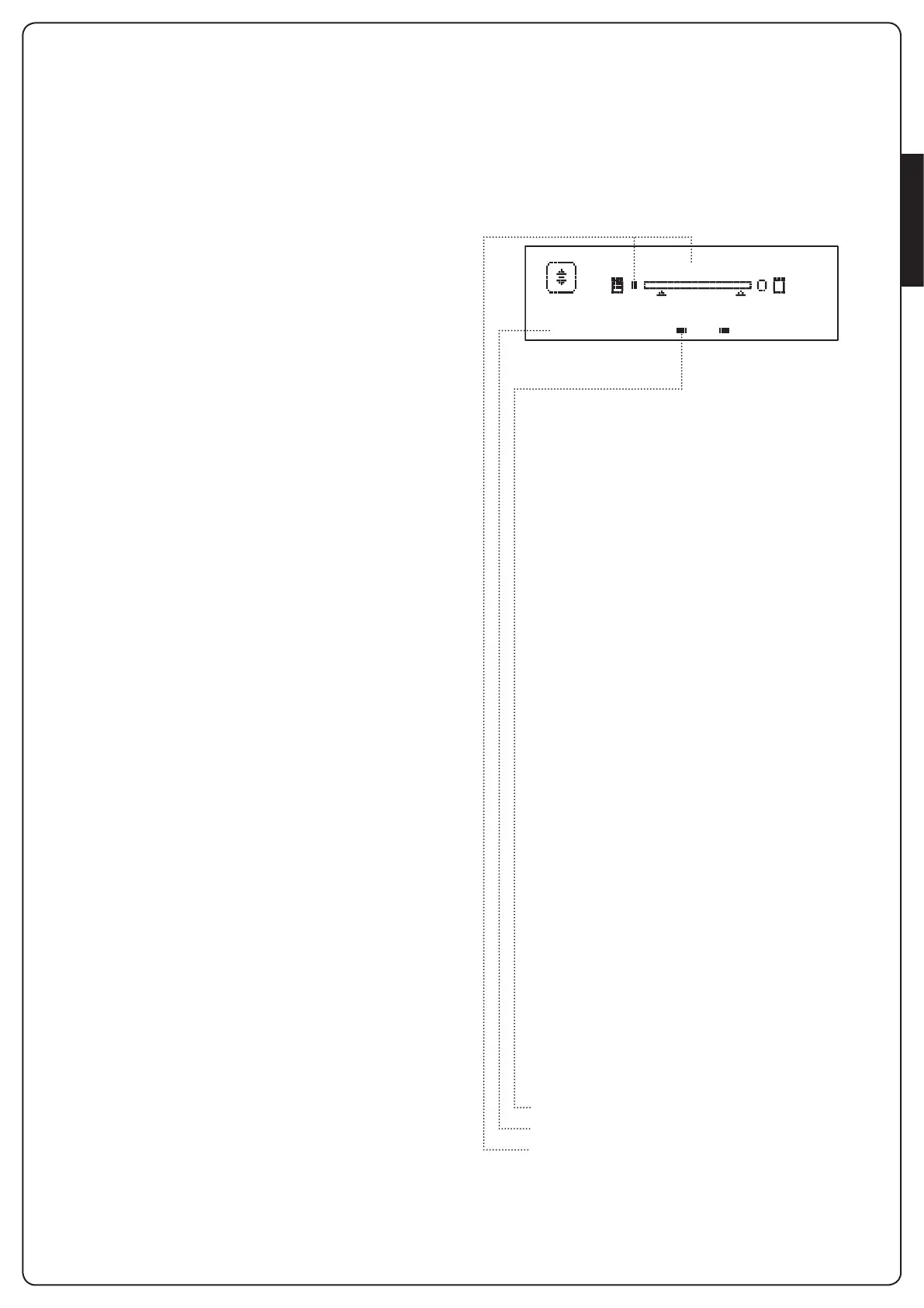
7 - CONTROL PANEL
Whenthepowersupplyisturnedonthedisplayshowsin
sequencethefollowinginformation:
1. Firmwareversionofthemicro-controlleroftheunit
2. Firmwareversionofthemicro-controlleroftheinverter
3. Serialnumber
4. Currentlanguageset
Herefollowingisthecontrolpanel:
i1
o
i2
o
i3
o
f1
ATTESA
f2 c1
o
c2
o
Thecontrolpanel(instandbymode)displaysthe
physicalstateofthecontactstotheterminalboardand
programmingbuttons:
I1
ING1input
I2
ING2input
I3
ING3input
F1
PHOTOCELL1input
F2
PHOTOCELL2input
C1
RIBB.1input
C2
RIBB.2input
Thedotdisplayedbelowtheabbreviationsofinputs
indicatesthestatusoftheinput:
• FULLdot:contactclosed
• EMPTYdot:contactopen
Intheupperpartofthedisplaythestatusofthe
automationsystemisshown:
• Themessage(e.g.WAITING)indicatesthestatusofthe
unit
• Thebarunderthemessageindicatesthepositionofthe
gatewithrespecttothelimitswitch
• Thedottotheleftofthebarshowstheclosinglimit
switch
• Thedottotherightofthebarindicatestheopening
limitswitch
• Thearrowontheleftindicatesthestatusofthedevice
connectedtotheterminalH3
• Thearrowontherightindicatesthestatusofthedevice
connectedtotheterminalH4
Thedotofthelimitswitchesandthearrowsoftheinputs
H3andH4indicatetheinputstatus:
• Arrow/FULLdot:closedcontact
• Arrow/EMPTYdot:opencontact
Intheexampleshownabovethedisplayindicatesthat:
• ThecontactofF1-F2inputsisclosed
• ThecontactofI1-I2-I3-C1-C2inputsisopen
• Thegateislockedandinstandbymode,waitingfora
command
WAITING