Vacon Plc Phone: +358-(0)201 2121 Fax: +358-(0)201 212 205
Service: +358-40-8371 150 E-mail: vacon@vacon.com
Page 24
VV
VV
V
aconacon
aconacon
acon
Multi-purpose Control Application IIMulti-purpose Control Application II
Multi-purpose Control Application IIMulti-purpose Control Application II
Multi-purpose Control Application II
2. 32. 3
2. 32. 3
2. 3
DIB4 functionDIB4 function
DIB4 functionDIB4 function
DIB4 function
Selections are the same as in 2
. .
. .
. 2 except :
10:10:
10:10:
10: Multi-Step contact closed = Selection 1 active
speed select 1
11
11
1
1:1:
1:1:
1: U
in
/I
in
digital selection for frequency reference
13:13:
13:13:
13: Fieldbus control: Selection between I/O and fieldbus control
14:14:
14:14:
14: Parameter 1.5 / Uin
15:15:
15:15:
15: Parameter 1.5 / Iin
2. 42. 4
2. 42. 4
2. 4
DIB5 functionDIB5 function
DIB5 functionDIB5 function
DIB5 function
Selections are the same as in 2
..
..
. 2 except :
10:10:
10:10:
10: Multi-Step contact closed = Selection 2 active
speed select 2
11
11
1
1:1:
1:1:
1: Motor pot. contact closed = Reference decreases until the contact is
UP opened
13:13:
13:13:
13: Fieldbus control: Selection between I/O and fieldbus control
2. 52. 5
2. 52. 5
2. 5
DIB6 functionDIB6 function
DIB6 functionDIB6 function
DIB6 function
Selections are the same as in 2
..
..
. 2 except :
10:10:
10:10:
10: Multi-Step contact closed = Selection 3 active
speed select 3
11
11
1
1:1:
1:1:
1: Motor pot. contact closed = Reference decreases until the contact is
DOWN opened
13:13:
13:13:
13: Fieldbus control: Selection between I/O and fieldbus control
Note! Note!
Note! Note!
Note! (
ParPar
ParPar
Par
. 2.3, 2.4, 2.5. 2.3, 2.4, 2.5
. 2.3, 2.4, 2.5. 2.3, 2.4, 2.5
. 2.3, 2.4, 2.5): In the fieldbus control par. 10.1 = 1 and 10.2 = 0.
2. 62. 6
2. 62. 6
2. 6
UU
UU
U
inin
inin
in
signal rangesignal range
signal rangesignal range
signal range
0 = Signal range 0—+10 V
1 = Custom setting range from custom minimum (par. 2
..
..
. 4) to custom
maximum (par. 2
..
..
. 5)
2 = Signal range -10—+10 V , can be used only with Joystick control
2. 72. 7
2. 72. 7
2. 7
UU
UU
U
inin
inin
in
custom setting minimum/maximum custom setting minimum/maximum
custom setting minimum/maximum custom setting minimum/maximum
custom setting minimum/maximum
2. 82. 8
2. 82. 8
2. 8
With these parameters, U
in
can be set for any input signal span within 0—10 V.
Minimum setting: Set the U
in
signal to its minimum level, select parameter 2
..
..
. 4,
press the Enter button
Maximum setting: Set the U
in
signal to its maximun level, select parameter 2
..
..
. 5,
press the Enter button
Note!Note!
Note!Note!
Note! These parameters can only be set with this procedure (not with the Browser
buttons)
2. 92. 9
2. 92. 9
2. 9
UU
UU
U
inin
inin
in
signal inversionsignal inversion
signal inversionsignal inversion
signal inversion
Parameter 2. 9 = 0, no inversion
of analogue U
in
signal.
Parameter 2. 9 = 1, inversion
of analogue U
in
signal.
2. 102. 10
2. 102. 10
2. 10
UU
UU
U
inin
inin
in
signal filter timesignal filter time
signal filter timesignal filter time
signal filter time
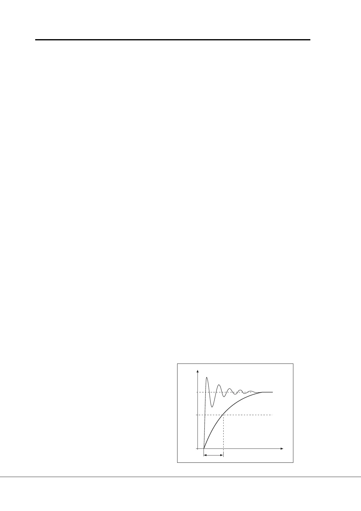
Filters out disturbances from the
incoming analogue U
in
signal.
Long filtering time makes regula-
tion response slower.
See figure 6-6.
%
100%
63%
Par. 2. 10
t [s]
UD009K37
Filtered signal
Unfiltered signal
Figure 6-6 U
in
signal filtering.

 Loading...


