Vacon Plc Phone: +358-(0)201 2121 Fax: +358-(0)201 212 205
Service: +358-40-8371 150 E-mail: vacon@vacon.com
Page 6
VV
VV
V
aconacon
aconacon
acon
Multi-purpose Control Application IIMulti-purpose Control Application II
Multi-purpose Control Application IIMulti-purpose Control Application II
Multi-purpose Control Application II
5.2 Description of Group 1 parameters 5.2 Description of Group 1 parameters
5.2 Description of Group 1 parameters 5.2 Description of Group 1 parameters
5.2 Description of Group 1 parameters
1. 1, 1. 21. 1, 1. 2
1. 1, 1. 21. 1, 1. 2
1. 1, 1. 2
Minimum / maximum frequencyMinimum / maximum frequency
Minimum / maximum frequencyMinimum / maximum frequency
Minimum / maximum frequency
Defines frequency limits of the frequency converter.
The default maximum value for parameters 1
..
..
. 1 and 1
..
..
. 2 is 120 Hz. By setting 1
. .
. .
. 2 =
120 Hz when the device is stopped (RUN indicator not lit) parameters 1
..
..
. 1 and 1
..
..
. 2
are changed to 500 Hz. At the same time the panel reference resolution is changed
from 0.01 Hz to 0.1 Hz.
Changing the max. value from 500 Hz to 120 Hz is done by setting the parameter
1
..
..
. 2 = 119 Hz when the device is stopped.
1. 3, 1. 41. 3, 1. 4
1. 3, 1. 41. 3, 1. 4
1. 3, 1. 4
Acceleration time 1, deceleration time 1:Acceleration time 1, deceleration time 1:
Acceleration time 1, deceleration time 1:Acceleration time 1, deceleration time 1:
Acceleration time 1, deceleration time 1:
These limits correspond to the time required for the output frequency to
accelerate from the set minimum frequency (par. 1
..
..
. 1) to the set maximum
frequency (par. 1
. .
. .
. 2).
1. 51. 5
1. 51. 5
1. 5
Reference selectionReference selection
Reference selectionReference selection
Reference selection
00
00
0 Analogue voltage reference from terminals 2—3, e.g. a potentiometer
11
11
1 Analogue current reference trom terminals 4—5, e.g. a transducer.
22
22
2 Reference is formed by adding the values of the analogue inputs
33
33
3 Reference is formed by subtracting the voltage input (U
in
) value
from the current input (I
in
) value.
44
44
4 Reference is formed by subtracting the current input (I
in
) value from the
voltage input (U
in
) value.
55
55
5 Reference is the formed by multiplying the values of the analogue inputs
66
66
6 Joystick control from the voltage input (U
in
).
WW
WW
W
arning!arning!
arning!arning!
arning! Use only -10V—+10 V signal range. If a custom or 0—10 V signal
range is used, the drive starts to run at the max. reverse speed if the
reference signal is lost.
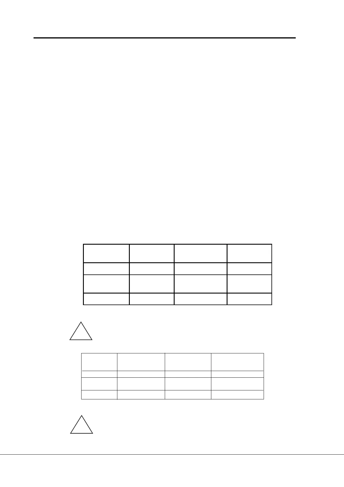
77
77
7 Joystick control from the current input (I
in
).
Signal range Max reverse Direction change Max forward
speed speed
0—20 mA 0 mA 10 mA 20 mA
Custom Par. 2
..
..
. 13 x 20 mA In the middle of Par. 2
..
..
. 14 x 20 mA
custom range
4—20 mA 4 mA 12 mA 20 mA
WW
WW
W
arning!arning!
arning!arning!
arning! Use only 4—20 mA signal range. If custom or 0—20 mA signal range
is used, the drive runs at max. reverse speed if the control signal is lost.
Set the reference fault (par. 7
. .
. .
. 2) active when the 4—20 mA range
is used, then the drive will stop to the reference fault if the reference
signal is lost.
!
!
Signal range
Max reverse
speed
Direction change
Max forward
speed
0—10 V 0 V 5 V +10 V
Custom Par. 2.7 x 10 V
In the middle of
custom range
Par. 2.8 x 10 V
-10 V—+ 10 V -10 V 0 V +10 V