VV
VV
V
aconacon
aconacon
acon Page 43
Multi-purpose Control Application IIMulti-purpose Control Application II
Multi-purpose Control Application IIMulti-purpose Control Application II
Multi-purpose Control Application II
Vacon Plc Phone: +358-(0)201 2121 Fax: +358-(0)201 212 205
Service: +358-40-8371 150 E-mail: vacon@vacon.com
f
I
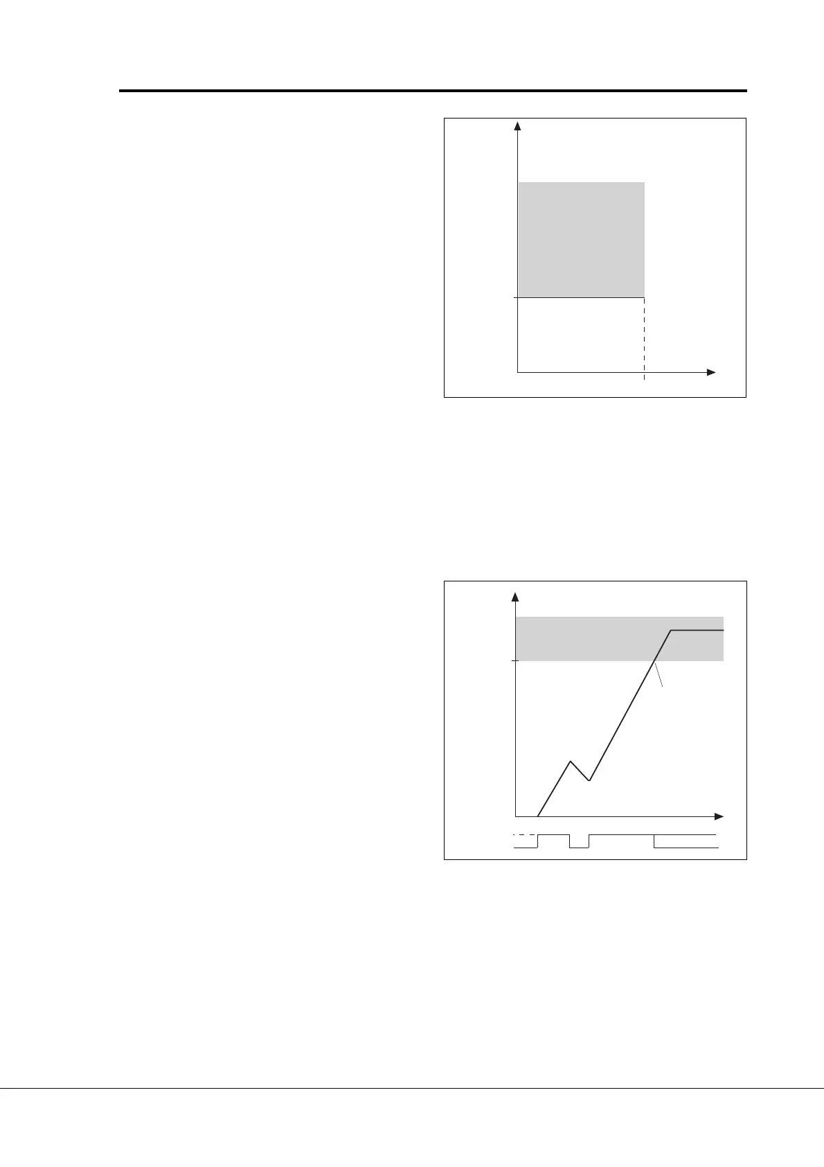
Par. 7. 11
Par. 7. 13
UMCH7_11
Stall area
Figure 6-28 Setting the stall
characteristics.
7. 127. 12
7. 127. 12
7. 12
Stall timeStall time
Stall timeStall time
Stall time
The time can be set between 2.0—120 s.
This is the maximum allowed time for a stall stage. There is an internal up/down
counter to count the stall time. Refer to figure 6-29.
If the stall time counter value goes above this limit the protection will cause a trip
(refer to parameter 7
..
..
. 10).
Par. 7. 12
UMCH7_12
Trip area
Time
Stall time counter
Stall
No stall
Trip/warning
par. 7. 10
Parameters 7. 14— 7. 17, Underload protectionParameters 7. 14— 7. 17, Underload protection
Parameters 7. 14— 7. 17, Underload protectionParameters 7. 14— 7. 17, Underload protection
Parameters 7. 14— 7. 17, Underload protection
GeneralGeneral
GeneralGeneral
General
The purpose of motor underload protection is to ensure that there is load on the motor when the
drive is running. If the motor loses its load there might be a problem in the process, e.g. a broken
belt or dry pump.
Motor underload protection can be adjusted by
setting the underload curve with parameters
7
. .
. .
. 15 and 7
..
..
. 16. The underload curve is a squared
curve set between zero frequency and the field
weakening point. The protection is not active below
5Hz (the underload counter value is stopped). Refer
to figure 6-30.
7. 17. 1
7. 17. 1
7. 1
11
11
1
Stall current limitStall current limit
Stall current limitStall current limit
Stall current limit
The current can be set to 0.0—
200% x I
nMotor
.
In a stall stage the current has to
be above this limit. Refer to figure
6-28. The value is set as a
percentage of the motor's name
plate data, parameter 1
. .
. .
. 13,
motor's nominal current. If
parameter 1
..
..
.13 is adjusted, this
parameter is automatically
restored to the default value.
7. 137. 13
7. 137. 13
7. 13
Maximum stall frequencyMaximum stall frequency
Maximum stall frequencyMaximum stall frequency
Maximum stall frequency
The frequency can be set between
1—f
max
(par. 1
..
..
. 2).
In a stall state, the output
frequency has to be smaller than
this limit. Refer to figure 6-28.
Figure 6-29 Counting the stall time.