Vacon Page 1 1 (1 5 )
I/ O-expander board installation (Vacon CXS-range)
Vacon Plc Tel: +3 5 8 -2 0 1 21 21 Fax: +3 5 8 -2 0 1 2 1 2 2 0 5
Service: +3 5 8 -4 0 -8 37 1 1 50 E-mail: vacon@vacon.com
http:/ / w ww.vacon.com
4 CON TROL CON N ECTION S
4.1 Vacon CX100OPT
Signal from
motor thermistors * )
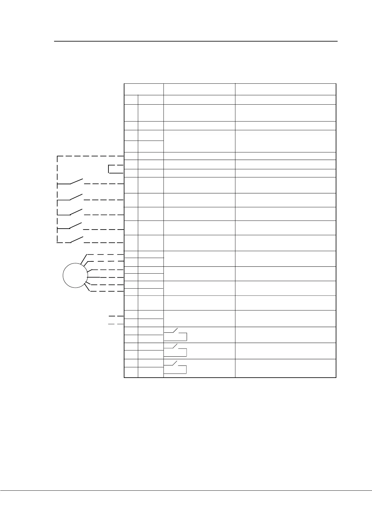
Figure 4 -1 Control connections of Vacon CX1 0 0 O PT.
Terminal Signal Description
2 0 1 + 1 0 V
ref
Reference output Voltage for a potentiometer, etc.
2 0 2 U
in
+ Analogue input, voltage N ot in use
range 0 —1 0 V DC
203 GN D I/ O ground G round for reference and controls
2 0 4 I
in
+ Analogue input, current N ot in use
2 0 5 I
in
- range 0 —2 0 mA
206 +2 4 V Control voltage output Voltage for switches, etc. max. 5 0 mA
207 GN D I/ O ground G round for reference and controls
208 CMC Common for DIC1 -DIC5 Connect to G N D or + 2 4 V
209 DIC1 External fault Contact open = no fault
(closing contact) Contact closed = fault
210 DIC2 Run disable Cont. open = start of motor enabled
Cont. closed= start of motor disabled
211 DIC3 Acceler. / Decel. time Contact open = time 1 selected
selection Contact closed = time 2 selected
212 DIC4 Jogging speed selection Contact open = no action
Contact closed = jogging speed
213 DIC5 Fault reset Contact open = no action
Contact closed = fault reset
214 DI6 A+ Pulse input A
215 DI6 A- (differential input)
216 DI7 B+ Pulse input B 9 0 degrees phase shift compared
217 DI7 B- (differential input) to pulse input A
218 DI8 Z+ Pulse input C one pulse per one revolution
219 DI8Z- (differential input)
2 2 0 I
out
+ Analogue output Programmable
0 —2 0 mA/ R
L
max. 50 0 Ω (M otor current as default value)
221 TI+ Thermistor input
2 2 2 TI -
2 2 3 RO 3 / 1 Relay output 3 READY
2 2 4 RO 3 / 2
2 2 5 RO 4 / 1 Relay output 4 RUN
2 2 6 RO 4 / 2
2 2 7 RO 5 / 1 Relay output 5 FAULT
2 2 8 RO 5 / 2
*) N OTE! Thermistor input (terminals 2 2 1 and 2 2 2 ) must be shorted if not used.
Enco-
der
 Loading...


