Page 6 (1 5 ) Vacon
I/ O-expander board installation (Vacon CXS-range)
Vacon Plc Tel: +3 58 -2 01 2 1 2 1 Fax: +3 5 8-20 1 2 1 2 2 05
Service: +3 5 8 -4 0 -8 37 1 1 50 E-mail: vacon@vacon.com
http:/ / w ww.vacon.com
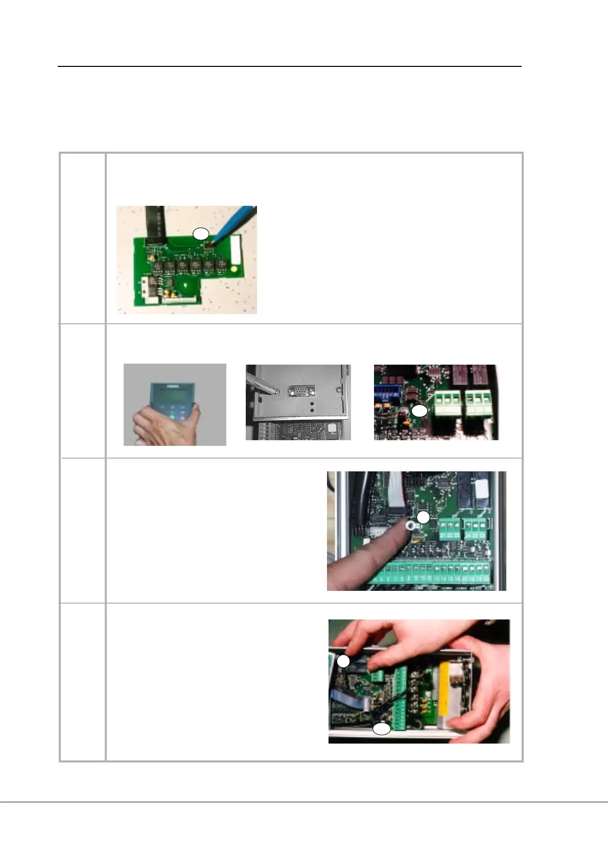
Table 3-2 . I/ O -expander board installation (continues ...).
1
2
4
Remove the control panel, control panel base (4 screws) and the jumper X4 from the
control board.
3
3.2 IN STALLATION
I/ O -repeater board (1 ) should be installed above the control board inside the frequency con-
verter. The I/ O -expander board (1 0 ) and I/ O -interface board (1 1 ) should be installed in the
option box. Follow the instructions below (see Table 3 -2 ).
Check that the jumper for I/ O -repeater board (1) is in the right position in terminal X5 (3).
The position of the jumper must be chosen according to the I/ O -expander board (11)
:
- If I/ O -expander board CX1 0 1 O PT or 1 0 3 O PT
is in use, jumper must be in position A.
- If I/ O -expander board CX1 0 0 O PT or 1 0 2 O PT
is in use, jumper must be in position B.
- If one of the follow ing fielbus boards is in use:
CX2 0 0 O PT, CX2 01 O PT, CX2 02 O PT or
CX2 0 3 O PT, jumper must be in position C.
(Positon D is not in use).
X5
X4
M ake sure that the cable of the control panel
cover is connected to the control board X1 ter-
minal. Connect the 4-pole power cable (4) to
the control board X5 terminal (The power cable
can also be connected to the X6 -terminal, if the
power cable from the power board is connected
to the X5 -terminal.)
Set the protection foil (5) above the control
board as shown in the picture. M ake sure that
the protection foil is correctly located, the hole
in the foil will must be located above the stand
sleeve.
X5
Remove the fixing screw from the control board
and replace it w ith the stand sleeve (7).
5
7
 Loading...


