Control Keypad vacon • 89
Local contacts: http://drives.danfoss.com/danfoss-drives/local-contacts/
6
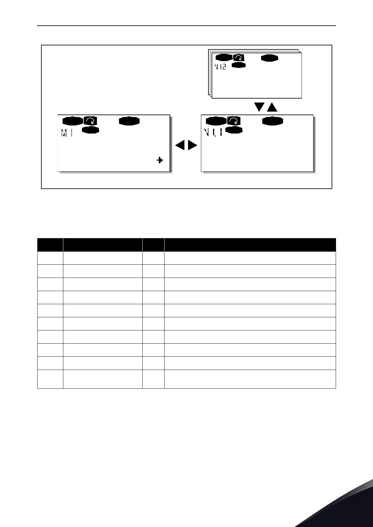
Figure 59. Monitoring menu
6.3.2 Parameter menu (M2)
Parameters are the way of conveying the commands of the user to VACON
®
NX Active Front End.
Parameter values can be edited by entering the Parameter Menu from the Main Menu when the
location indication M2 is visible on the first line of the display. The value editing procedure is
presented in Figure 60.
Pressing Menu button right once takes you to the Parameter Group Menu (G#). Locate the desired
parameter group by using the Browser buttons and press Menu button right again to see the group
and it‘s parameters. Use the Browser buttons to find the parameter (P#) you want to edit. Pressing
Table 32. Monitored signals
Code Signal name Unit Description
V1.1 Frequency reference Hz
V1.2 DC-link voltage V Measured DC-link voltage
V1.3 Unit temperature ºC Heat sink temperature
V1.4 Voltage input V AI1
V1.5 Current input mA AI2
V1.6 DIN1, DIN2, DIN3 Digital input statuses
V1.7 DIN4, DIN5, DIN6 Digital input statuses
V1.8 DO1, RO1, RO2 Digital and relay output statuses
V1.9 Analogue output current mA AO1
M1.17 Multimonitoring items
Displays three selectable monitoring values. See
Chapter 6.3.8.4, Multimonitoring items (P6.5.4).
V1
V14
READY
Local
13.95 Hz
READY
Local
13.95 Hz
READY
Lo ca l
RUN RUN
RUN
Monito r Output frequency
FreqReference
11204.emf
 Loading...


