INSTALLATION OF THE OPTAF BOARD vacon • 13
Local contacts: https://www.danfoss.com/en/contact-us/contacts-list/
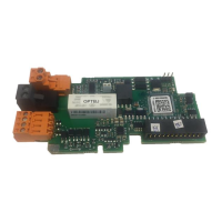
2.1 OPTAF board layout
Figure 1. The layout of the OPTAF board
2.2 Control board VB00761 layout
The revision of the control board VB00761 can be determined from the sticker on the board.
Figure 2.The layout of the control board VB00761
Jumper X10 for selecting
thermistor short
circuit supervision
+24V+
+24V-
+24V+
+24V-
SD1
SD2
Thermistor input
Thermistor Input: Thermistor
active > 4000 ohm. After being
active, the fault can be reset if
resistance is < 2000 ohm.
Jumper wire X12
See Chapter 4.2.4.
STO inputs two
independent channels
Programmable
Relay
"NO/NC"
Programmable
Relay
"NO"
Ñ761JÌ3$ Í2AS{Ó
11966_00
761J190400002AS