13
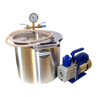
Photo 16: Vacuum cold trap.
The vacuum cold trap (Photo 16) consists of two tanks - the outer tank (5), where the deposition process takes place, and
the inner tank, in which the cooling agent (e.g. dry ice) is placed. The outer tank is equipped with the vacuum pump connecting
valve (1) and the vacuum chamber connecting valve (6). The vacuum pump connecting valve is equipped with an unsealing valve
(2) with an air filter. The inner tank has a polycarbonate lid. The wide flange of the inner tank (4) is also a cover for the outer
tank. The tightness of the vacuum cold trap is ensured by a blue silicone gasket put on the outer tank. Photo 17 shows the inner
tank, outer tank, blue silicone gasket and ice formed as a result of deposition.
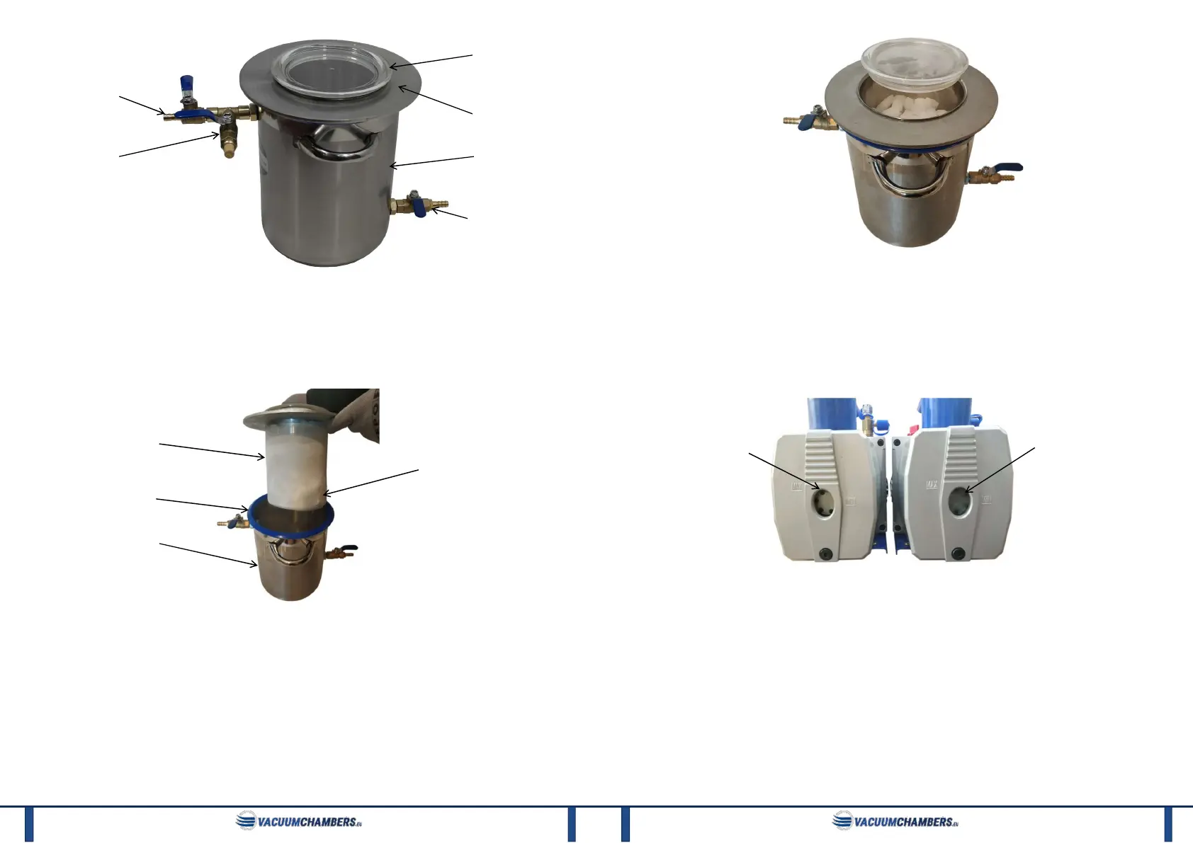
Photo 17: Inner tank, outer tank, silicone gasket and ice formed on the internal tank.
The inner tank lid limits the contact of the cooling agent with the environment. This slows down the cooling agent heating-
up speed, and thus prolong its useful life. However, it is not possible to completely prevent the heating of the cooling agent
during its use. Gases are released from the cooling agent as a result of heating. Allow these gases to escape from the inner tank,
as their accumulation may result in a dangerous pressure build-up in the inner tank. Therefore, the inner tank lid must not be
loaded with other objects, nor have a limited free lift. The cooling agent should be placed only in the cold trap internal tank
(Photo 18). After placing the cooling agent inside the cold trap, cover the inner tank with the lid.
deposition process
2
2. Unsealing valve.
3. Inner tank lid with a gasket.
4. Inner tank flange.
5. Outer tank.
6. Vacuum chamber connecting valve.
3
4
5
outer tank
14
Photo 18: Vacuum cold trap with dry ice inside.
The deposition takes place inside the outer tank. The outer tank receives air sucked from the vacuum chamber. Air rapidly
cools down as a result of contact with a very cold inner tank wall. This causes vapour deposition on the inner tank walls. Photo
17 shows the ice formed in the deposition process. The purified air from the cold trap goes then to the vacuum pump.
Photo 19 shows the result of the cold trap work. Vacuum pumps visible in this photo were used for water degassing in the
vacuum chamber. The pump on the left was working in a vacuum set with a vacuum cold trap between the chamber and the
pump. As a result, the air was cleaned of water vapour and prevented the vacuum pump from contaminating with water. The oil
remained clear. In the pump, shown on the right side of the photo, no cold trap was used. The vacuum pump was contaminated
with water and the oil became damp and turbid.
Photo 19: The result of the cold trap work - oil in vacuum pumps clarity (left: clear oil when using a cold trap, right: turbid oil
when no cold trap is used).
To use the vacuum cold trap:
1) Connect the cold trap to the vacuum chamber (connect one end of the pneumatic hose to the vacuum chamber connecting
valve and the other end to the vacuum chamber exhaust air valve).
2) Connect the cold trap to the vacuum pump (connect one end of the pneumatic hose to the vacuum pump connecting valve,
and the other end to the vacuum pump).
3) Place the inner tank centrally in the outer tank. The outer tank blue gasket should not protrude beyond the inner tank
flange.
4) Open the inner tank by removing the inner tank lid.
5) Fill the inner chamber with a cooling agent (e.g. dry ice):
a. Read cooling agent safety instructions and follow the information contained therein.
b. Put on cold resistant gloves.
c. Put the cooling agent into the cold trap inner tank.
d. Close the inner tank with the lid (without pressing the lid down).
6) Open the pump connecting valve and chamber connecting valve (place the valves handles parallel to the valves).
the sight glass
the sight glass
 Loading...