Instructions for Use, Installation and Servicing ecoMAX pro 17
7 Flue
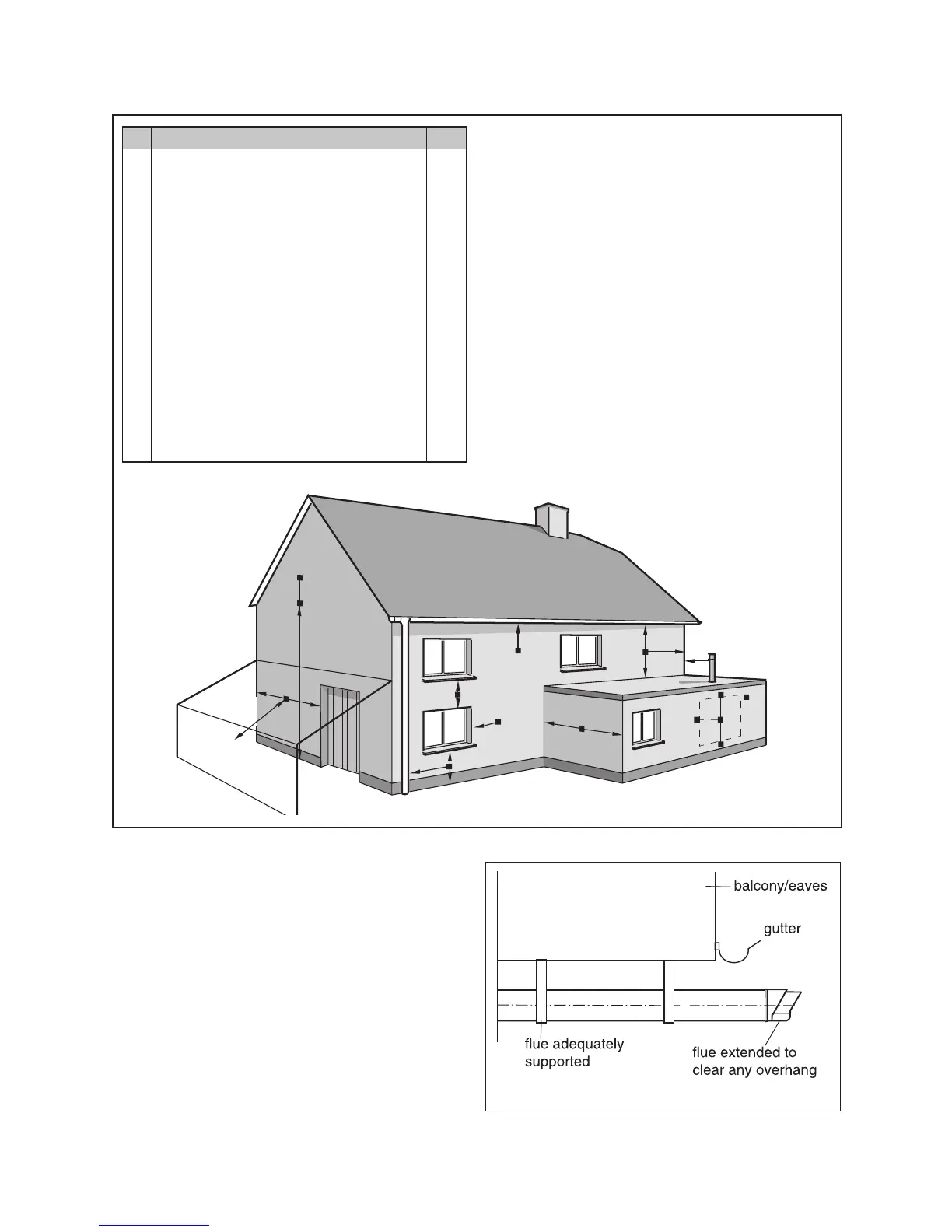
1) In addition, the terminal should not be nearer
than 150mm to an opening in the building fabric
formed for the purpose of accommodating a built-in
element such as a window.
2) Dimension B,C and D; These clearances may
be reduced to 25 mm without affecting the
performance of the boiler. In order to ensure that
the condensate plume does not affect adjacent
surfaces the terminal should be extended as shown
in Fig 7.4.
3) Dimension F; This clearance may be reduced
to 25 mm without affecting the performance of
the boiler. However, in order to ensure that the
condensate plume does not affect adjacent surfaces
a clearance of 300 mm is preferred.
4) BS 5440-1 It is recommended that a fanned flue
terminal should be positioned as follows:
a) at least 2m from an opening in a building directly
opposite, and
b) so that the products of combustion are not
directly directed to discharge across a boundary.
For IE, recommendations are given in the current
edition of IS 813.
Fig 7.2
12677
Fig 7.1
12676
TERMINAL POSITION mm
A
1)
Directly below an opening, above an opening
or horizontal to an opening i.e. air brick,
opening window or other, etc 300
B Below gutters, soil pipes or drain pipes 75
2)
C Below eaves 200
2)
D Below balconies 200
2)
E From vertical drain pipes and soil pipes 25
F From internal or external corners 300
3)
G Above ground, roof or balcony 300
H From a surface facing a terminal 600
4)
I From a terminal facing a terminal 1200
K Vertically from a terminal on the same wall 1500
L Horizontally from a terminal on the same wall 300
M Distance from adjacent wall for vertical Flue 500
 Loading...