EasyManuals Logo

Vaillant ecoMAX SERIES Instructions For Installation And Servicing

Vaillant ecoMAX SERIES
56 pages
To Next Page IconTo Next Page
To Previous Page IconTo Previous Page
Page #7 background imageLoading...
Page #7 background image
7
Boiler Specification 2
Instructions for installation and servicing ecoMAX 7
2.3 Boiler connections
Fig. 2.2
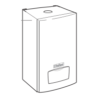
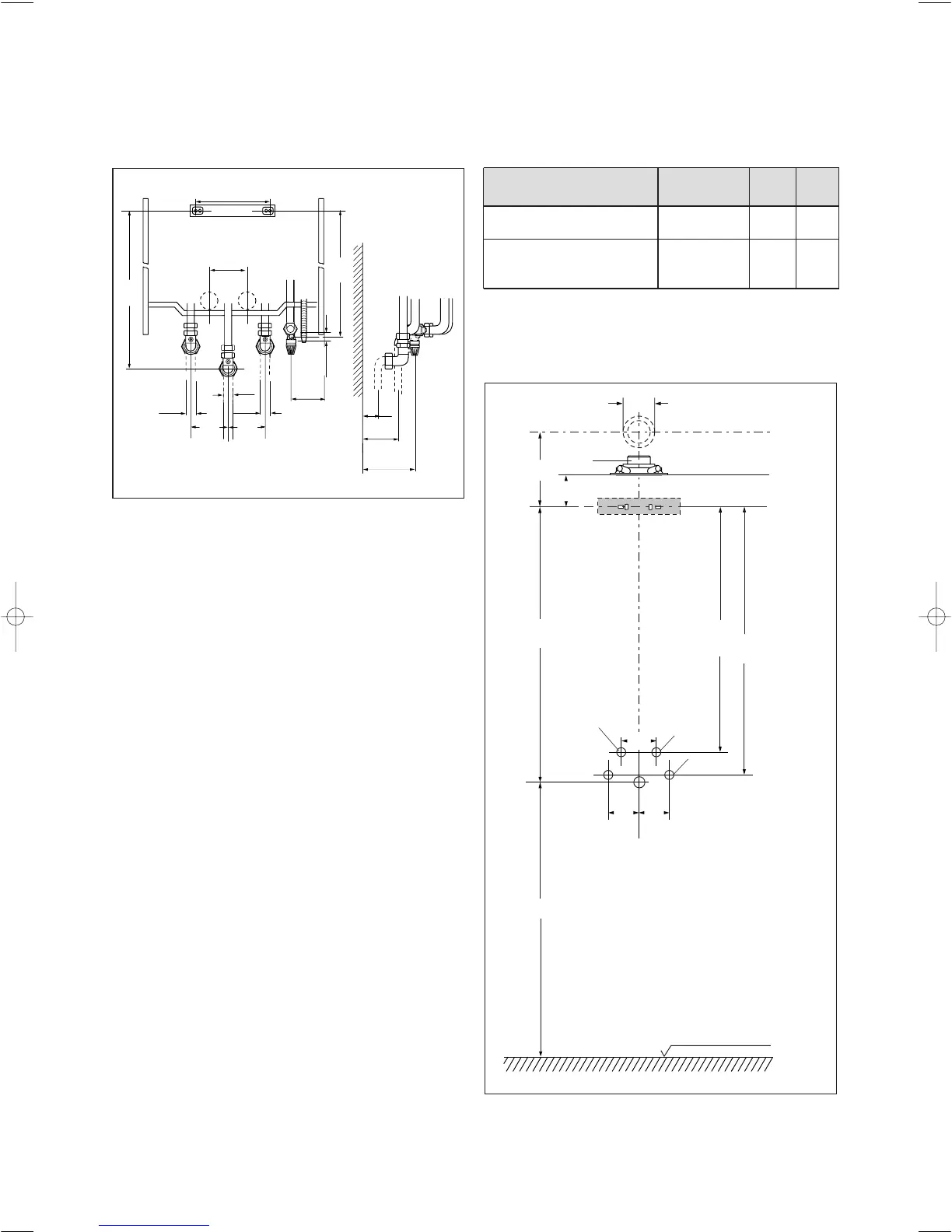
2.4 Scale drawing and fitting dimensions
Dimensions when combined with A ØB C*
the following system comp.: with 87° elbow
air/flue system Ø 60/100 235 60/100 _
air/flue system Ø 80/125 253 80/125 _
VANTAGE 120 _ _ 1101
VANTAGE 150 _ _ 1101
VANTAGE 200 _ _ _
Tab. 2.1 Dimensions used in combinations
*) Note: Dimension C must be observed if a Vaillant VANTAGE 120, 150 and
200 hot–water tank is to be installed under the heating unit.
Fig. 2.3 Fitting dimensions
94
1
Top edge of appliance
750
C
A
Air/flue duct centrer
3
717
Dimensions for
embedded installation
100 100
4
684
120
6
Ø B
Ø22
Ø22
25
33.5
100100
Ø 15
750
703
150
79
70
Ø15
113
83 41 77_12 GB04.04.qxd 22.09.2004 12:34 Uhr Seite 7

Table of Contents

Other manuals for Vaillant ecoMAX SERIES

Questions and Answers:

Question and Answer IconNeed help?

Do you have a question about the Vaillant ecoMAX SERIES and is the answer not in the manual?

Vaillant ecoMAX SERIES Specifications

General IconGeneral
BrandVaillant
ModelecoMAX SERIES
CategoryBoiler
LanguageEnglish

Related product manuals