0020308118_05 Installation and maintenance instructions 61
13.7.3 Replacing the pump head
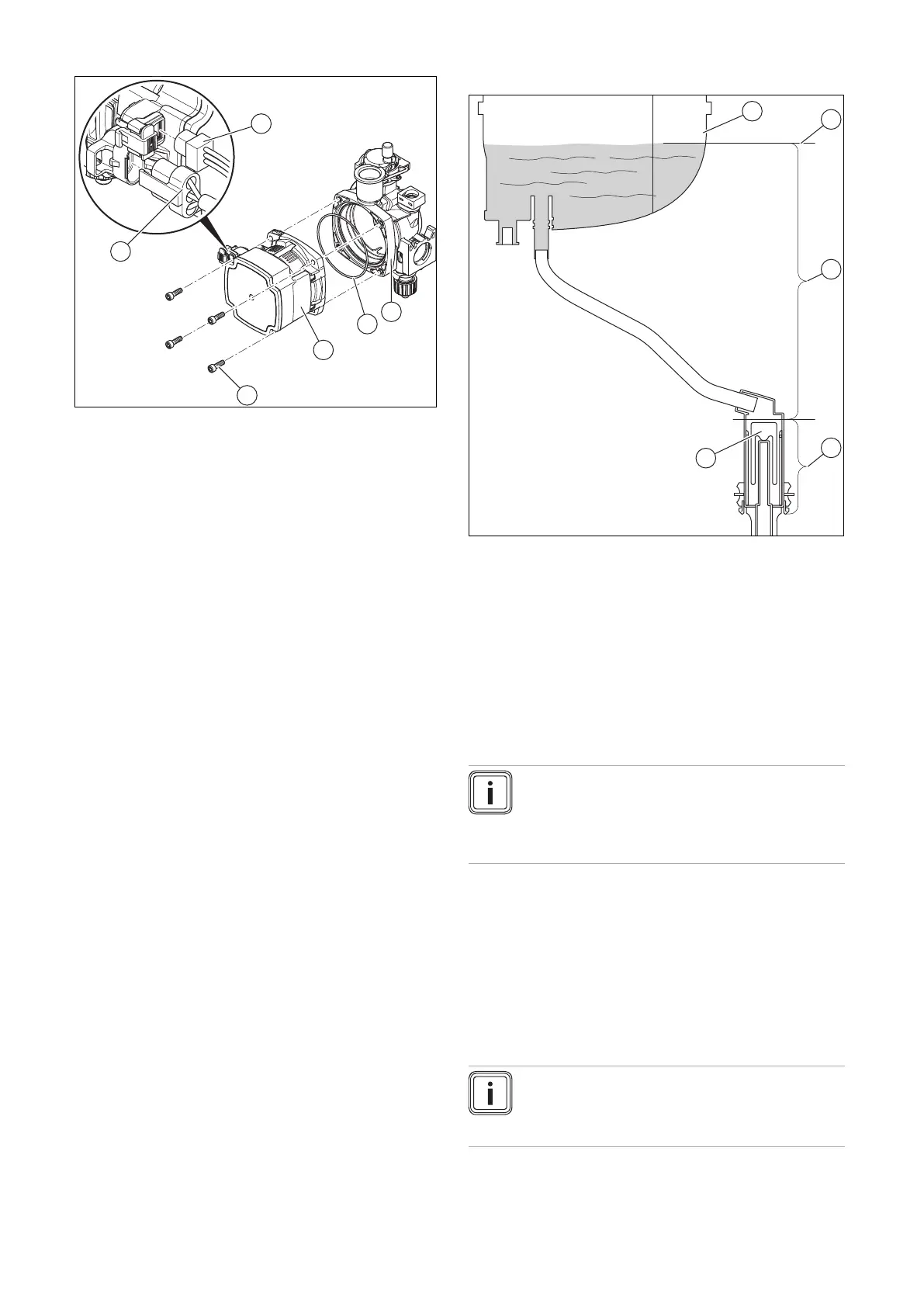
1. Pull out the plugs (5) and (6) from the pump head.
2. Undo the four screws (4).
3. Remove the pump head (3).
4. Check the inside of the lower section of the pump (1)
for dirt.
Result 1:
Dirt is present
▶ Clean the inside of the lower section of the pump.
Result 2:
Dirt is magnetic
▶ Check the installed magnetite separator.
5. Replace the O-ring (2).
6. Secure the new pump head using four new screws at
the lower section of the pump.
7. Tighten the four screws in a cross-wise pattern until
the pump head on the lower section of the pump fits
uniformly. Tightening torque, see appendix.
8. Reconnect the two plugs on the pump head.
9. Fill the heating installation. (→ Section 9.9)
10. Purge the heating installation. (→ Section 9.10)
11. Check the product for tightness. (→ Section 9.17)
13.7.4 Eliminating the condensate discharge
blockage (F.028 or F.029)
1 Heat cell
2 Height of the ignition
and control electrode
3 Accumulation of con-
densate in the event of
a blockage
4 Normal condensate
volume
5 Float
If fault F.028 or F.029 occurs as a result of a frozen con-
densate discharge pipe or another blockage cause, main-
tenance work must be carried out on the condensate siphon
(→ Section 12.8.5). It is not sufficient to thaw the condensate
discharge pipe.
Note
During maintenance work, note that a large quant-
ity of condensate has collected above the float in
the condensate siphon and this may escape when
you remove the lower section of the siphon.
Proceed as follows:
▶ Thaw the condensate discharge pipe and clean it.
▶ Service the condensate siphon.
▶ Start up the product again.
▶ If the condensate discharge pipe is clear and fault mes-
sage F.028 or F.029 persists, carry out maintenance
work on the heat cell (→ Section 12.7).
13.7.5 Replacing the burner
Note
Never replace the burner only, but always replace
the burner flange, the burner and the control elec-
trode, as well as all of the seals.
 Loading...


