28 Installation and maintenance instructions 0020244997_07
7.11 Flue installation
7.11.1 Installing and connecting the air/flue pipe
1. You can find out which air/flue pipes may be used
by consulting the enclosed set-up instructions for the
air/flue system.
2. Observe the information on positioning the air/flue ter-
minal.
Condition: Installation in damp rooms
▶ You must connect the product to a room-sealed air/flue
system. The combustion air must not be taken from the
installation site.
Caution.
Risk of poisoning due to escaping flue
gas.
Mineral-oil-based greases can damage the
seals.
▶ Instead of grease, use only water or com-
mercially available soft soap to aid install-
ation.
3. Install the air/flue pipe using the set-up instructions.
7.11.2 Replacing the connector for the air/flue pipe
as required
1. Replace the connector for the air/flue pipe as required.
The product-specific standard equipment is listed un-
der Technical data.
2. Remove the connector for the air/flue pipe.
(→ Page 28)
3. If required, install the connector for the air/flue pipe,
80/125 mm diameter. (→ Page 28)
7.11.2.1 Removing the connector for the air/flue pipe
1. Insert a screwdriver into the slot between the test
points.
2. Press the screwdriver carefully down (1.).
3. Turn the connector anti-clockwise (2.) as far as it will
go and then remove it by pulling it upwards (3.).
7.11.2.2 Installing the connector for the air/flue pipe,
80/125 mm diameter
1. Remove the connector for the air/flue pipe.
2. Insert the alternative connector. In doing so, pay atten-
tion to the latching lugs.
3. Turn the connector clockwise until it clicks into position.
7.12 Electrical installation
Only qualified electricians may carry out the electrical install-
ation.
Danger!
Risk of death from electric shock!
Power supply terminals L and N remain live
even if the on/off button is switched off:
▶ Disconnect the product from the power
supply by switching off all power supplies
at all poles (electrical partition with a con-
tact gap of at least 3 mm, e.g. fuse or cir-
cuit breaker).
▶ Secure against being switched back on
again.
▶ Wait for at least 3 minutes until the capa-
citors have discharged.
▶ Check that there is no voltage.
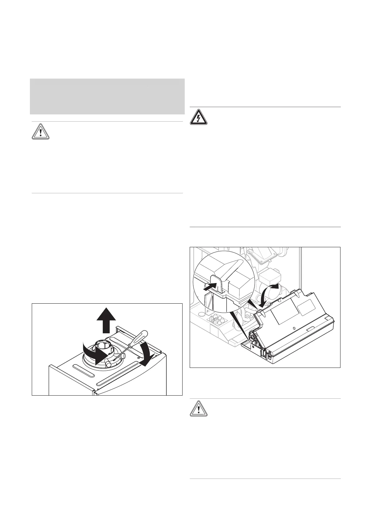
7.12.1 Opening the electronics box
▶ Open the electronics box as shown in the figure.
7.12.2 Carrying out the wiring
Caution.
Risk of material damage caused by incor-
rect installation.
Mains voltage at incorrect terminals and plug
terminals may destroy the electronics.
▶ Do not connect any mains voltage to the
eBUS terminals (+/-).
▶ Only connect the mains connection cable
to the terminals marked for the purpose.

 Loading...


