66 Installation and maintenance instructions 0020244997_07
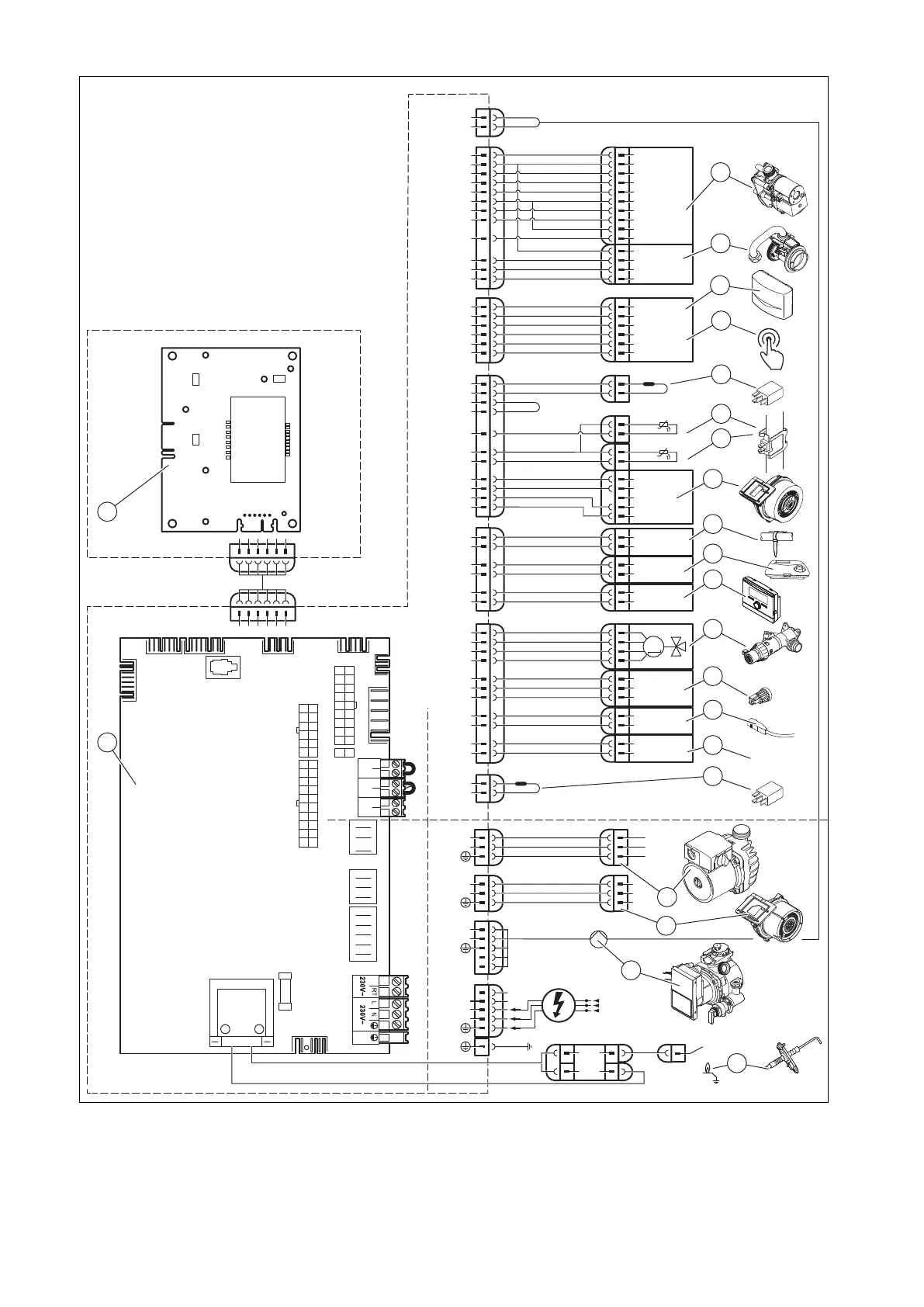
H.2 Wiring diagram, product for heating mode only, ≥ 37 kW
X18
X51
X20
X1
X11
24V
230V~
24V
230V~
X41
X25
6
5
4
3
2
1
X22
6
5
4
3
16
1
12
4
X2
13
11
14
3
1
4
L
N
L
N
L
RT
*
N
X16
L
N
1
2
3
1
2
3
8
17
7
18
6
4
3
1
M
C1
C2
16
4
3
17
5
7
8
5
4
2
1
Masse
PWM
Hallsignal
+24V
15
2
13
12
Burner Off BUSRT 24V
X100
12
6
9
4
2
10
1
11
3
5
1
2
7
8
2
4
X24
17
3
X30
X40 X51 X35
X31
X22
X90
2
1
T2
Fuse
X12
X25
X2
Opt
X16
Fan
X11
X18
CH Pump
X24
X20
–
+
24V=
RT BUS
Burner
off
X100
X1
X41
5
X51
2
1
10
20
10
19
3
4
17
18
14
15
13
12
11
8
16
6
7
9
21
1 Main PCB
2 Control panel PCB
3 Gas valve assembly
4 Mass flow sensor
5 Outdoor temperature sensor, flow temperature
sensor (optional, external), DCF receiver
6 Circulation pump remote control
7 Power coding resistor
8 Return temperature sensor

 Loading...


