40 Installation and maintenance instructions 0020244997_07
10.3 Setting the pump output
1. Navigate to Menu → Installer level → Diagnostics
menu → D.014 Pump speed target value and confirm
by pressing .
2. Set the required pump output.
Condition: Low loss header installed
▶ Switch off the speed regulation and set the pump output
to a fixed value.
10.3.1 Remaining feed head of the pump
10.3.1.1 Pump characteristic line for VU 126, VU 156,
VU 186
400
300
200
100
0
0 200 400 600 800 1000 1200 1600
1800
1400
Flow rate
[
l/hr
]
Remaining feed head
[hPa]
100% PWM
85%
70%
60%
53%
10.3.1.2 Pump characteristic line for VU 246, VUW
196, VUW 256
0
400
300
200
100
0
50
150
250
350
200 400 600 800 1000 1200 1400
Remaining feed head
[hPa]
Flow rate
[
l/hr
]
100% PWM
80%
70%
60%
53%
10.3.1.3 Pump characteristic line for VU 306, VUW
306, VUW 356
400
300
200
100
0
0 200 400 600 800 1000 1200 1600
1800
1400
Flow rate
[
l/hr
]
Remaining feed head
[hPa]
100% PWM
85%
70%
60%
53%
10.3.1.4 Pump characteristic line for VUW 246, VUW
326
400
300
200
100
0
0 200 400 600 800 1000 1200 1600
1800
1400
Remaining feed head
[hPa]
Flow rate
[
l/hr
]
100% PWM
85%
70%
60%
53%
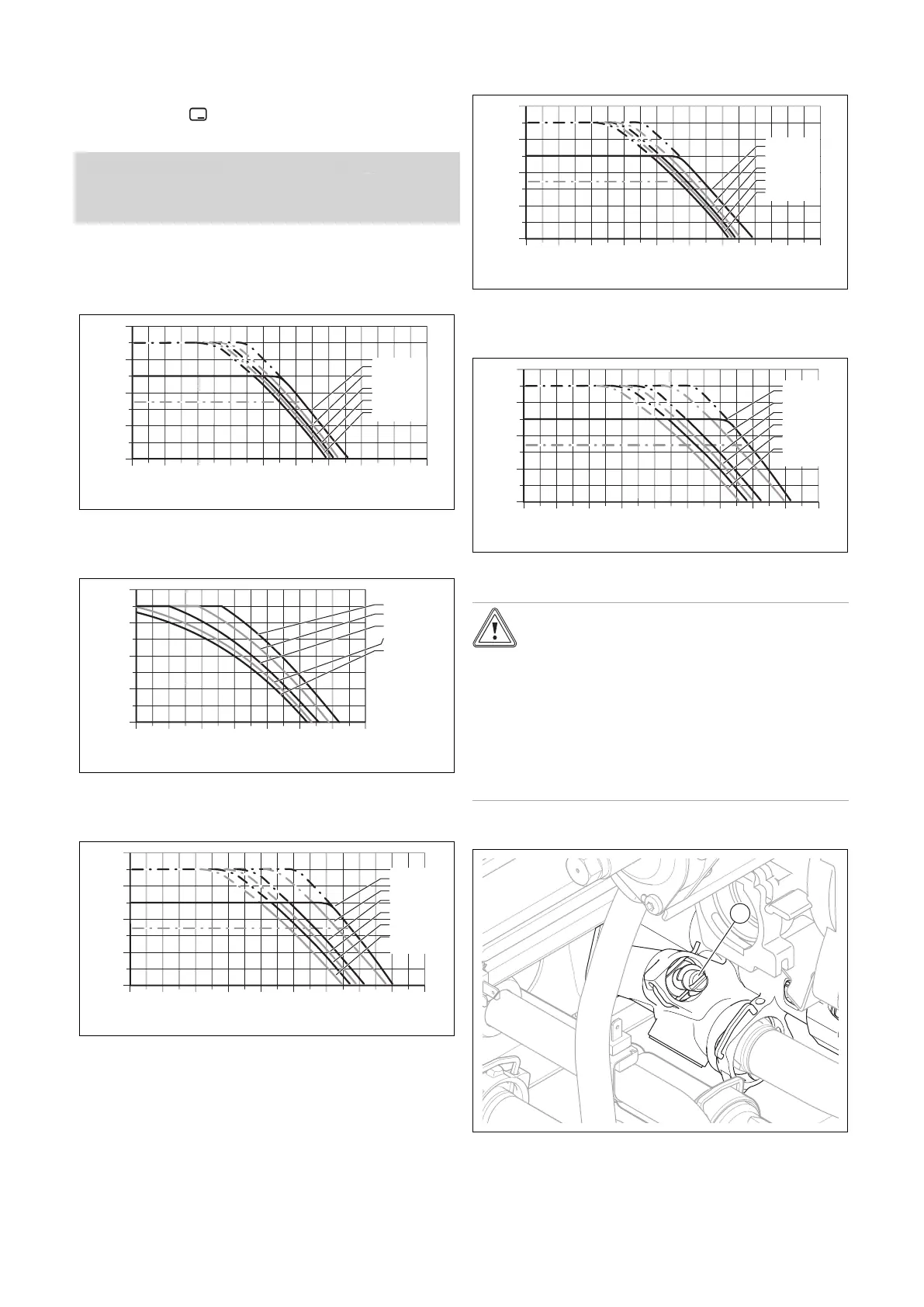
10.3.1.5 Pump characteristic line for VU 376, VU 386,
VUW 286, VUW 386
400
300
200
100
0
0 200 400 600 800 1000 1200 1600
1800
1400
Remaining feed head
[hPa]
Flow rate
[
l/hr
]
Minimum
with Auto
100% PWM
85%
70%
60%
53%
10.4 Setting the bypass valve
Caution.
Risk of material damage caused by incor-
rect setting of the high-efficiency pump
If the pressure at the bypass valve is in-
creased (by turning it clockwise) and the
pump output is set to less than 100%, the
product may not operate correctly.
▶ In this case, set the pump output to
5 = 100% using diagnostics code D.014.
▶ Remove the front casing. (→ Page 23)
▶ Regulate the pressure using the adjusting screw (1).

 Loading...


