30
6
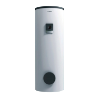
Select the system diagram number
applicable to the system installed. Refer to
page 32 for relevant system configuration
settings in accordance to the schematic
drawing of the system installed.
7
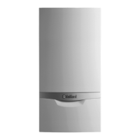
Depending on your system, scroll through
and select the solar setting applicable.
8
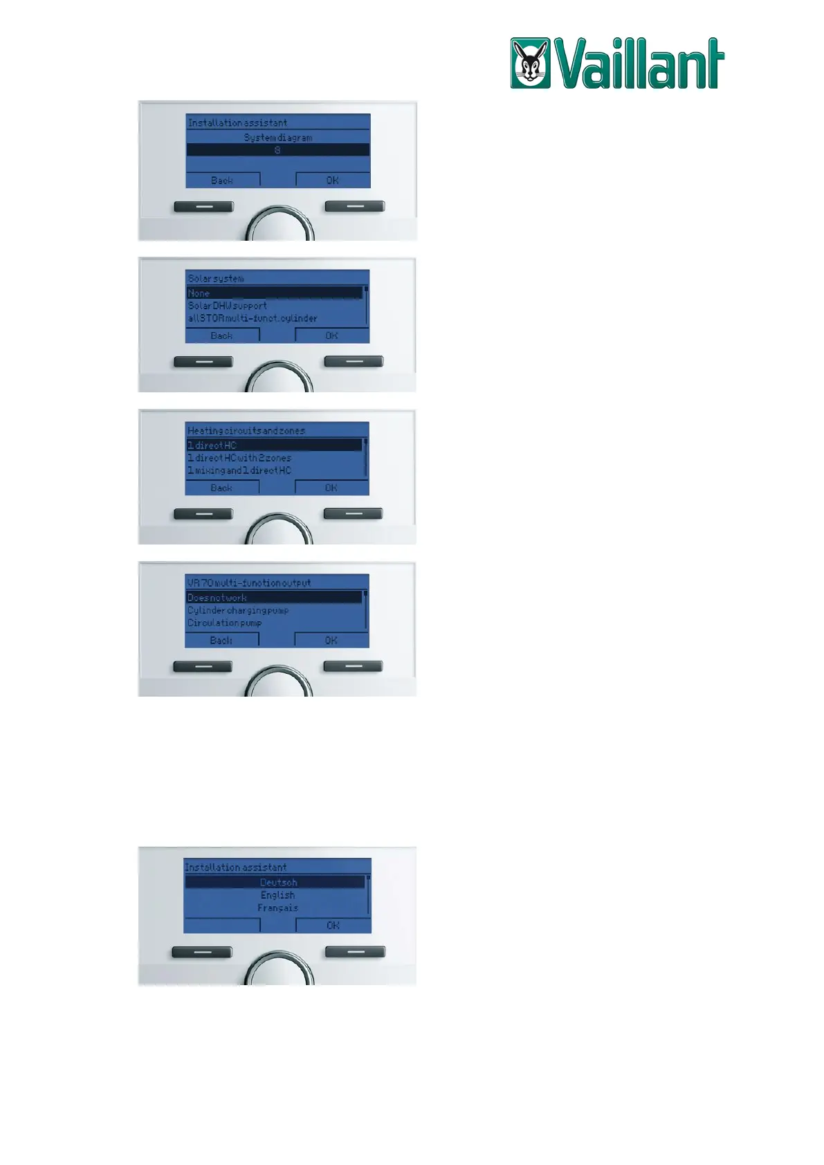
Depending on your system, scroll through
and select the heating zone configuration
that is installed.
9
If this screen is displayed, select the
assignment for the multi-function output
terminal of the VR 70. Select ‘Does not
work’ if this terminal isn’t in use. Refer to
page 32 for relevant system configuration
settings in accordance to the schematic
drawing of the system installed.
The next screen will allow you to check the status of the required and optional sensor
terminals, it is recommended to scroll through the entirety of this screen and confirm
the statuses. Pressing ‘OK’ will then take you to the finishing screen of the installation
assistant, where you will have the option to go to the system configuration menu, go to
the home screen or test the sensors and actuating terminals.
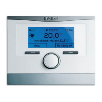
VRC 700/4 & Earlier Models
1
Use the rotary knob to scroll through the
different language options and then press
‘OK’ (the selection button below the
display, on the right) to select your
language of choice.
 Loading...