0020200905_02 Operating and installation instructions 9
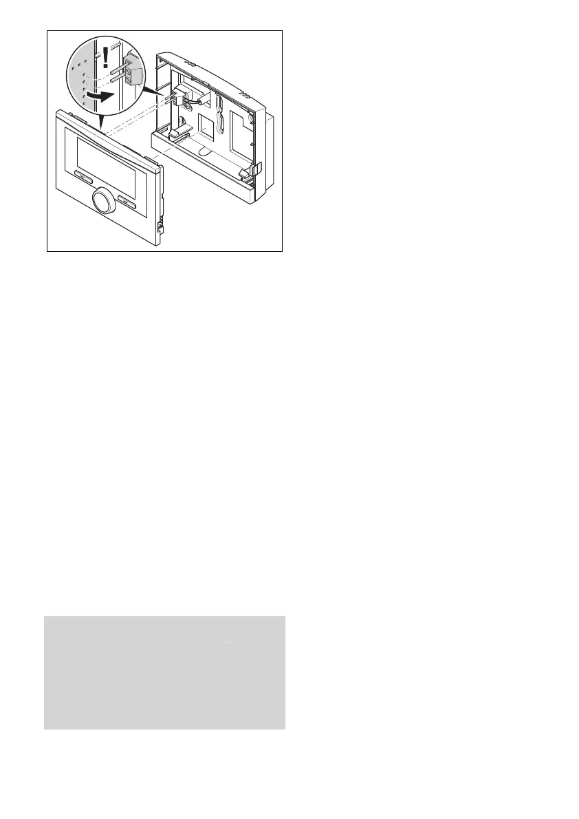
4. Carefully push the remote control unit
into the wall base.
3.5 Electrical installation
Only qualified electricians may carry out
the electrical installation.
3.5.1 Polarity
When connecting the eBUS line, there is
no need to pay attention to the polarity. If
the connection cables are switched over,
communication will not be adversely af-
fected.
3.5.2 Connecting the remote control
unit to a heat generator
1. At lengths of 10 m or more, power
supply cables and bus lines must be
laid separately.
2. When opening the electronics box in
the heat generator, proceed as de-
scribed in the installation instructions
for the heat generator.
Condition: The heat generator is not connected to
the eBUS via the VR 32.
▶ Connect the eBUS line to the eBUS
terminals in the wall base of the remote
control unit.
▶
Connect the eBUS line to the eBUS
terminals in the heat generator.
3.6 Start-up
When you are operating the heating in-
stallation for the first time after installing
the electrical wiring, the installation assist-
ants for the system components and the
remote control unit start automatically.
All settings that you have applied using
the installation assistant can be changed
again at a later date via the level for the
end user and competent persons.
Installation assistant (→ Page 15)
3.6.1 Configuring the settings on the
remote control
1. Select the required language in the
Language function.
2. Enter the address the system control
needs in order to communicate with
the remote control unit in the Remote
control address function.
3.6.2 Configuring the settings on the
system control
1. If you would also like to use the room
temperature sensor in the remote
control unit, select the Temp. mod. or
Thermost. setting in the Room temp.
mod. function.
2. Specify in which zone the remote con-
trol unit has been installed.
3. Scroll through the display to the zone
in which the remote control unit has
been installed.
4. Reduce the setting in this zone to Yes
in the Zone activated function.
5. Assign the address for the remote
control unit that should be triggered
in the Zone assignment function in
this zone.
3.6.3 Changing the settings later
All settings that you have made via the in-
stallation assistant can be changed again
at a later date via the end user or installer
level.
Operating levels (→ Page 13)
Installer level (→ Page 16)
 Loading...