User's Guide ______________________________________________________________________
144 __________________________________________________________________M210784EN-E
0201-049
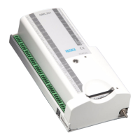
Figure 66 Dual RS-485 Module Default Jumper Locations
1006-102
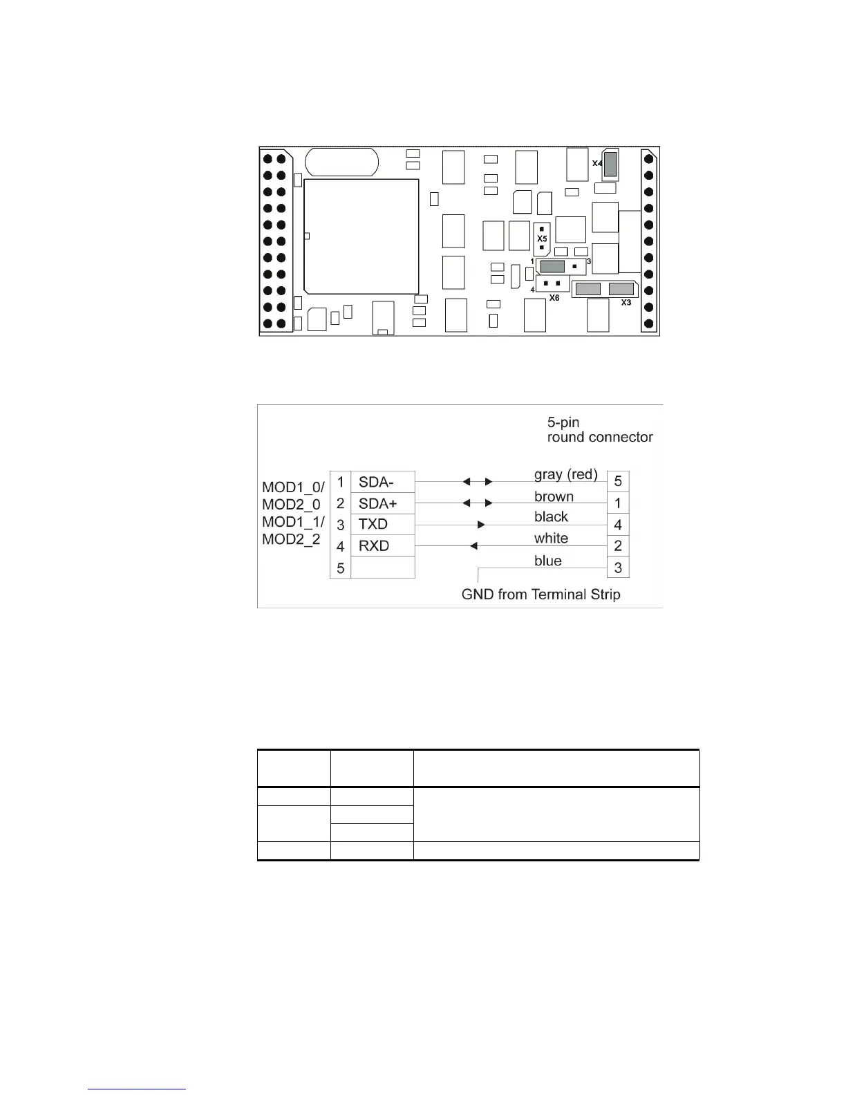
Figure 67 Dual RS-485 Wiring Diagram for RS-485 and RS-232
Figure 67 on page 144 provides a schematic wiring diagram for the
combination of the RS-485 and RS-232 connection. The correct jumper
settings for the channel B are listed in Table 34 on page 144.
Table 34 Jumper Settings for Channel B in the RS-232 Mode
Jumper Connected
Pins
Function
X3 2-3 Sets the RS-232 mode active for the channel B.
X6 1-4
2-5
X5 None The line terminating resistor is not in use at all.