QUICK REFERENCE GUIDE _________________________________________________________
Wiring
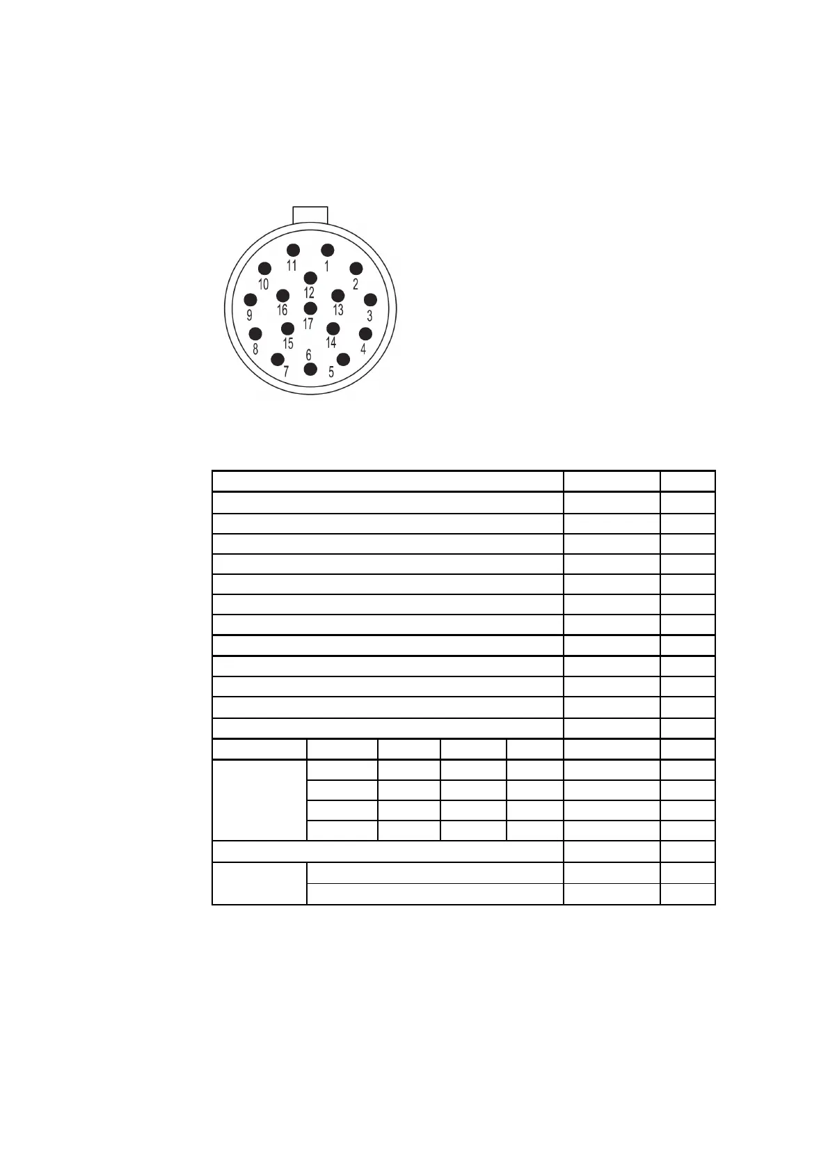
The figure below shows the pins of the 17-pin M23 Connector.
The table below shows how to connect Cable 2m (227567SP) and Cable 10m
(227568SP).
Power Supply Wire Colors Pin
Operating Power Supply White 1
Operating Power Supply Ground Gray-Pink 11
Heater Power Supply Gray 5
Heater Power Supply Pink 6
Heater Power Supply Ground Blue 7
Heater Power Supply Ground Red 8
Enclosure Ground Shield Shield
Analog Outputs
Analog Output AOUT2, Wind Direction Brown 2
Analog Output AOUT1, Wind Speed White-Green 13
Reference Input for AOUT2 (simulated potentiometer) White-Gray 17
Analog Output Ground Red-Blue 12
COM Port RS-232 RS-422 RS-485 SDI-12
RS232Rx RxB RxB - Green 3
RS232Tx TxB TxB Data Yellow 4
- TxA TxA - Brown-Green 14
COM2
- RxA RxA - White-Yellow 15
COM1 and COM2 Communication Ports Ground Violet 10
RS-485, B Black 9
COM1
(service port)
RS-485, A Brown-Yellow 16
6
___________________________________________________________________ M211218EN-B

 Loading...


