12 © 2000 Directed Electronics, Inc.
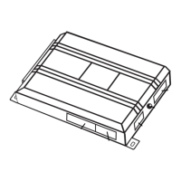
to a keyless entry system. This wire can also be connected to an optional momentary switch to activate the
remote start system.
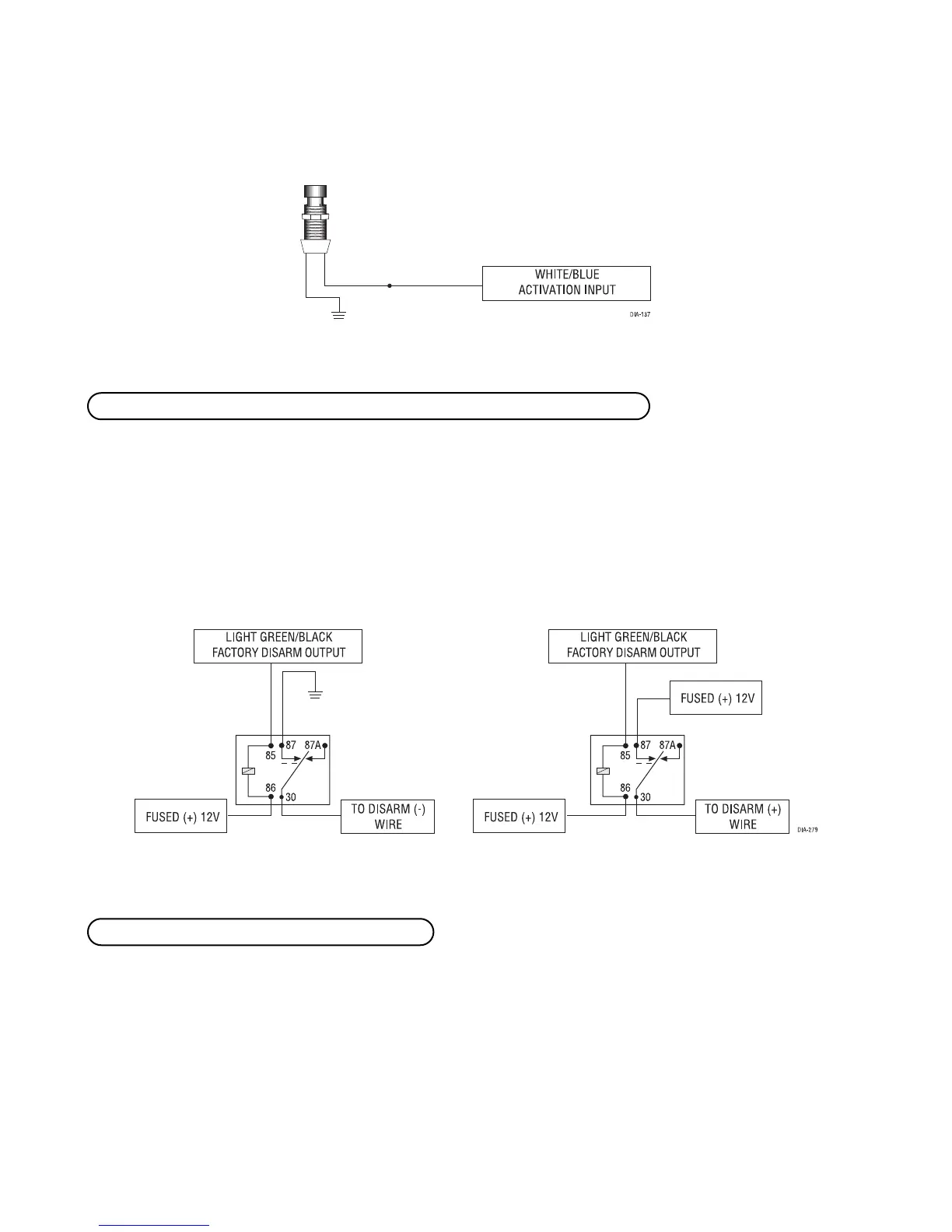
This wire sends a negative pulse every time the remote start is activated. This can be used to pulse the disarm
wire of the vehicle's factory anti-theft device. Use a relay to send a (-) or (+) pulse to the disarm wire as shown
in the following diagrams. This wire can also be used as a special accessory output. (See Feature Descriptions
section of this guide.)
Relay for Negative (-) Disarm Wire Relay for Positive (+) Disarm Wire
Connect the H1/4 YELLOW (+) ignition output wire to the ignition input of the remote controlled security or
keyless entry system. The remote start interface will prevent the host system from sensing that the ignition is
on during remote start operation.
H1/4 YELLOW (+) ignition output to RF system
H1/3 LIGHT GREEN/BLACK (-) factory security disarm/special accessory output
 Loading...