33
SIX WIRE OPERATION USING VR102 ROOM STATIONS
Although System One is designed to operate optimally using 8 wire Hook-up, it will
also operate using 6 wire hook-up with the trade off that music will mute at all stations
during private communication. (With 8 wire hook-up music only mutes at the 2 stations
involved in communication)
To operate a system using 6 wire hook-up, the following is required.
Master Station (Special Order Only)
Jumpers are to be inserted on jumper pins L1 & L4 on main board of master.
Orange terminal must be linked to blue terminal at master.
Green terminal must be linked to white terminal at master.
Music lines (Green & Orange) are omitted.
Room Stations
Press “PRIVACY” and “MONITOR” buttons simultaneously to enter Program Mode.
Press “HOUSE” button to select “6 wire” mode. (Green LED off)
Press “CLEAR” button to exit Program Mode.
Music lines (MUS1 and MUS2) are omitted. (No wire links required at Room Stations)
The station will toggle between 6 wire mode (Green LED off) and 8 wire mode (Green LED on)
each time the “HOUSE” button is pressed while in program mode.
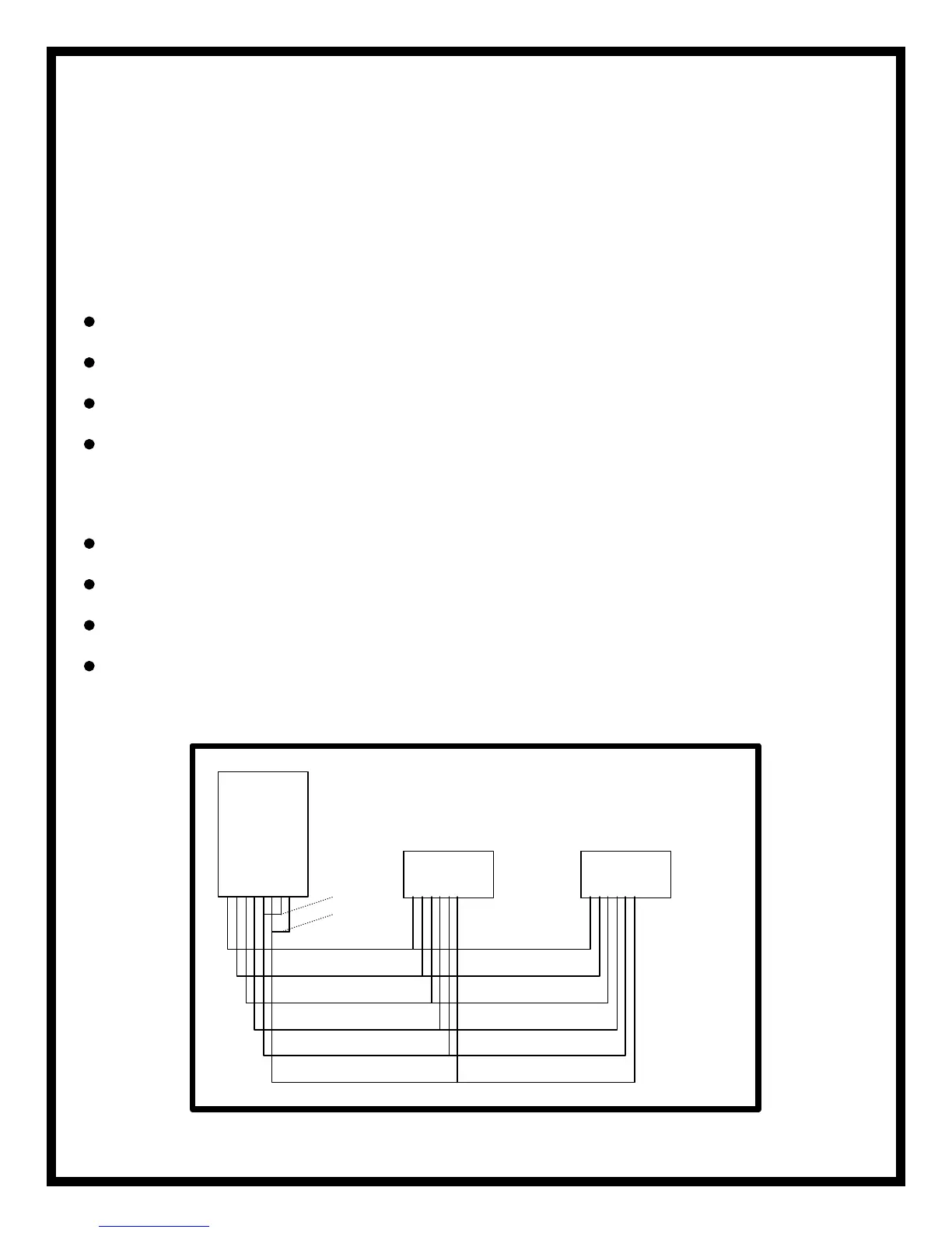
RED
BLACK
SHIELDED RED
SHIELDED WHITE
BLUE
WHITE
GREEN
ORANGE
POS
NEG
TC
VLC
COM1
COM2
MASTER
ROOM DOOR
(VR102)
NOTE: If using Auxiliary Input Jack Type B, connect green
& orange terminals of input jack to COM1 & COM2
terminals at Room Station.
Be sure to bridge 6 Wire Jumper (L1) on Input Jack
 Loading...
