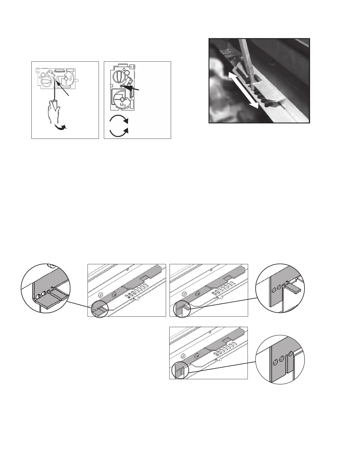
4. Adjust the pressure adjustment screw using a small
jeweller’s size fl at blade screwdriver—as shown
below—while the appliance is running at full input
to produce the manifold pressure, as per
Specifi cations table on page 1.
5. Check all the fi ttings for leaks.
6. Turn off the appliance, remove the manometer and
tighten the test tapping screw.
Adjust the air shutter
The air shutter lever is located in front of the fi rebox
behind the appliance front panel.
1. Tabs beside the lever must be repositioned accord-
ing to the gas used. With a screwdriver blade, bend
the tab pushing up or down according to the gas
used, as indicated below (these diagrams show the
aeration adjust in the fully closed position).
Front Face of Control Valve
Pry o
Plastic Cap
Front Face of
Control Valve
Pressure
adjustment
screw behind
plastic cap
Increases pressure
Decreases pressure
2. Adjust the shutter using a screwdriver as a lever to
slide the shutter left or right.
Complete the installation of the fi replace
Complete the installation of the fi replace following the
guidelines of the installation instructions supplied with
the appliance.
Fit the conversion labels
1. Fit the conversion label with new specifi cations
over the corresponding specifi cations on the data
plate located at under the short window on the card
marked Lighting/Operation Instructions.
2. Fit the label “This appliance was converted on... by...”
near the data label fi tted in 1.
3. Fit the label “This control has been converted...” on the
side of the appliance near the valve.
Closed
Open
Set air shutter
with a screwdriver
Designed and Manufactured by / for
Miles Industries Ltd.
190 – 2255 Dollarton Highway, North Vancouver, B.C., CANADA V7H 3B1
Tel. 604-984-3496 Fax 604-984-0246
www.valorfi replaces.com
Because our policy is one of constant development and improvement, details may vary slightly from those given in this publication.
LX1 and LX2 natural gas:
both tabs up
LX1 propane gas:
small tab up
LX2 propane gas:
both tabs down
4
 Loading...