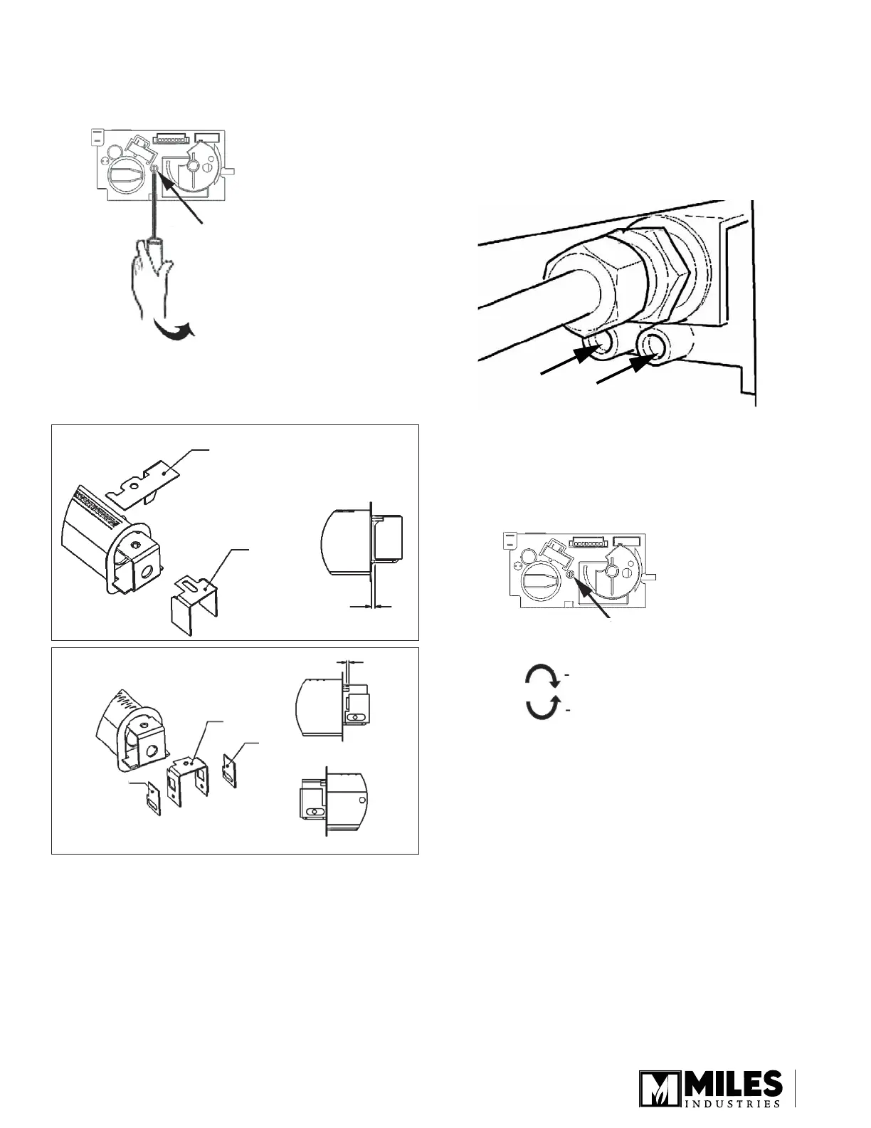
10. Lever off the small domed cap covering the
manifold pressure setting screw, on front face of
valve cover by using a screwdriver or similar.
11. Refi t the module to the appliance.
12. Fit the aeration shutter for the gas set as per
diagram.
Supply
pressure
test tapping
Manifold
pressure
test tapping
Front Face of Control Valve
Pry o
Plastic Cap
Front Face of Control Valve
Pressure Adjustment Screw
behind Cap
Increases Pressure
Decreases Pressure
13. Turn on gas supply and check for leaks using
soap solution. The minimum and maximum gas
supply pressure are indicated on page 1 and can be
verifi ed using the inlet supply pressure test tapping.
14. Using a small straight blade screwdriver, back off
the plug screw within the manifold pressure test
tapping. Fit a manometer to the manifold pressure
test tapping.
15. Light the appliance and turn up to full fi re. Check
for leaks downstream of the valve. Adjust the
manifold pressure setting screw according to
specifi cations indicated on page 1.
16. Turn appliance off. Remove the manometer and
tighten the test tapping screw. Refi t the domed plug.
17. Fit the data conversion label and signed conversion
label close to the rating plate. Fit the control
conversion label near the controls.
18. Re-install all ceramics, check that the appliance
operates correctly. Refer to main instructions.
Designed and Manufactured by / for
Miles Industries Ltd.
190 – 2255 Dollarton Highway, North Vancouver, B.C., CANADA V7H 3B1
Tel. 604-984-3496 Fax 604-984-0246
www.valorfi replaces.com
Because our policy is one of constant development and improvement, details may vary slightly from those given in this publication.
3000371
530LPG
530NG
320B293
3000220
3000220
4000682
3 mm AERATION GAP
2 mm AERATION GAP
0 mm AERATION GAP
3
 Loading...