612
Model/Modell
No/Nr. Page
/Seite
4(4)6000---875015.04.1998 39.6
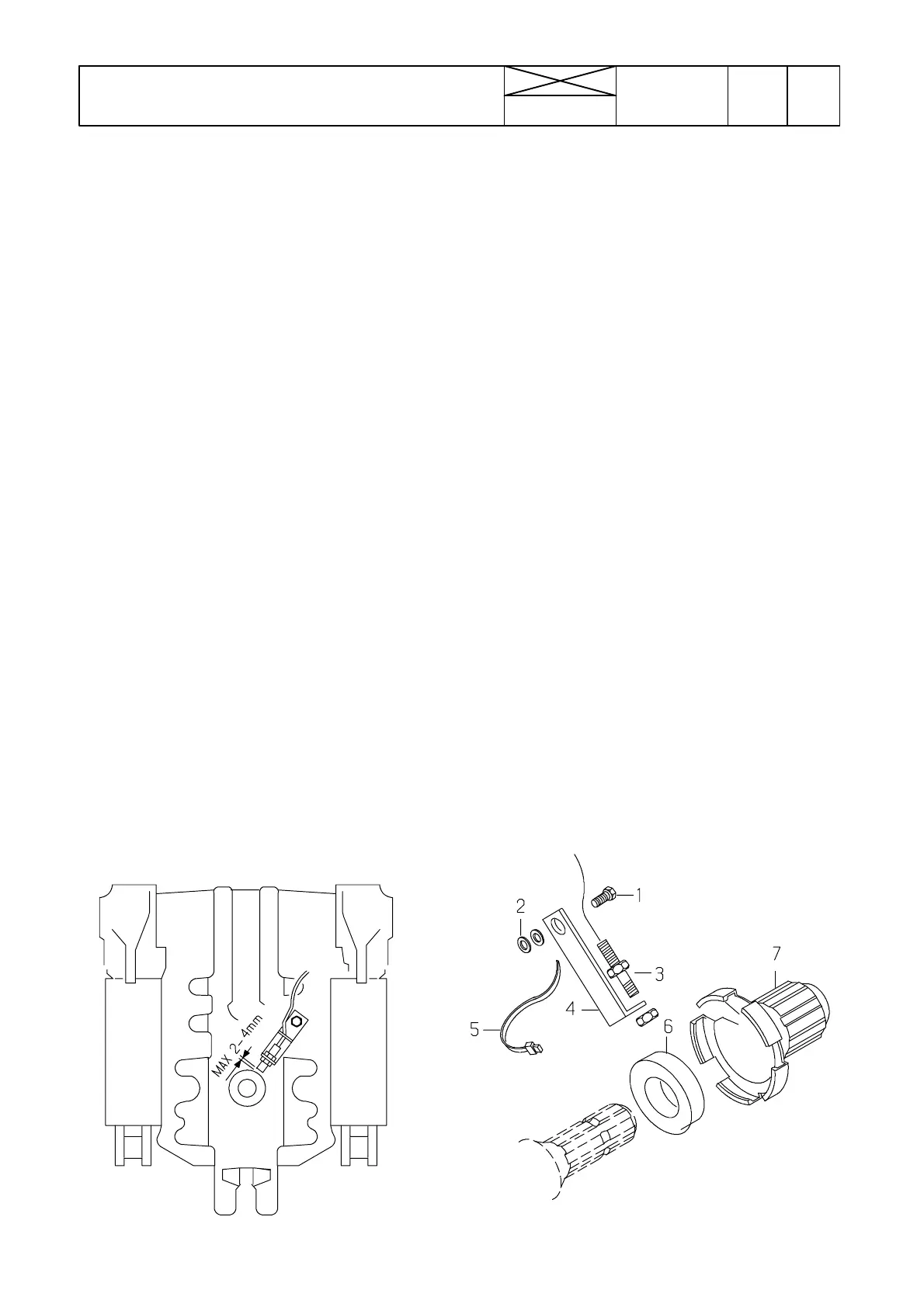
PTO REVS SENSOR, FITTING INSTRUCTION
MONTAGEANLEITUNG DES ZAPFWELLENGEBERS
08.06.1993
Sensor for PTO revs 32775300.......
--- This sensor is used as an optional equipment
for Agrodata. Then the switch S49 (see picture
B) selects PTO revs display or revs on an imple-
ment (if the implement has a revolution speed
sensor).
--- After fitting the sensor it must remain a free
radial space of 62 mm measured from the end of
the PTO shaft. (SFS---4572 standard: R 83 mm).
That is why all transmission shafts cannot be
used together with the PTO speed sensor.
FITTING:
--- Fa s t e n t h e m a g n e t 6 at the base of the PTO
shaft (ø 35mm type) (fixing screw on magnet).
--- Fasten the wire loom to the fastener with plastic
tie 5.
Fasten the fastener 4 to the threaded hole at the
rear side of the PTO housing (remove the protec-
tive plug). Fit between the fastener and housing
two washers. Direct the fastener towards the
shaft center point and tighten the screw.
--- Fit the sensor 3 so that the distance between
the sensor and the magnet becomes 3---4 mm.
Passthewirethroughthecabrearsidelead---in
point and connect wires to connector X54 poles
7, 8 and 9, see picture B.
Zapfwellendrehzahlgeber 32775300...
--- Dieser Geber ist eine Zusatzausrüstung der
Agrodata. Man kann dabei durch Betätigung des
Schalters S49 (Abb. B) entweder die Zapfwellen-
drehzahl oder die Drehzahl des Arbeitsgerätes
anzeigen (wenn dieses mit einem Drehzahlgeber
ausgestattet ist)
--- Nach Montage des Drehzahlgebers hat der Frei-
raum um das Ende der Zapfwelle einen Radius
von 62 mm (SFS---4572 Standard: 83 mm).
Aus diesem Grunde können bei eingebautem
Drehlzahlgeber nicht alle Gelenkwellentypen ver-
wendet werden.
--- E I NB AU:
--- Magnet 6 auf Zapfwelle montieren (paßt nur für
35 mm--- Zapfwelle). Befestigungsschraube im
Magneten.
--- Kabel 5 am Geberhalter 4 befestigen. Halter 4
mit Schraube 1 und zwei untergelegten Schei-
ben 2 am Zapfwellengehäuse befestigen. Halter
zur Wellenmitte ausrichten und Schraube anzie-
hen.
--- Geber 3 einbauen und Luftspalt auf 3---4 mm
einstellen. Kabel durch Durchführung im hinteren
Teil der Kabine ziehen und an Naben 7,8 und 9
der Verbindung X54 (Abb. B) anschlißen.
1 1 HA6356 Ruuvi Skruv Screw Schraube
2 1 JD0416 Aluslaatta Bricka Washer Scheibe
3 1 31703000 .Anturi Givare Sensor Geber
4 1 32775200 Kannatin Hållare Support Halter
5 2 SA1900 Side Band Band Band
6 1 32775100 Magneetti Magnet Magnet Magnet
7 1 32775400 Suojakuppi Skyddskopp Shield cup Schutz
 Loading...

