VANNER
Incorporated
Owner’s Manual
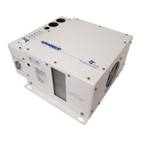
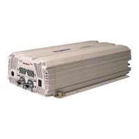
VTS Series 1500Watt 2 True Sine Wave Inverter/AC transfer Switch
1. Important Safety Information _______________________________________________________________ 3
1-1. General Safety Precautions _______________________________________________________________________ 3
1-2. Precautions When Working with Batteries ___________________________________________________________ 3
2. Features and Specifications ________________________________________________________________ 4
2-1. Standard Features _______________________________________________________________________________ 4
2-2. Typical AC Loads ________________________________________________________________________________ 4
2-3. Electrical Performance and Specifications ____________________________________________________________ 5
2-4. Mechanical Drawings ____________________________________________________________________________ 6
3. Installation and Operation _________________________________________________________________ 7
3-1. Front Panel Area: _______________________________________________________________________________ 7
3-1-2. ON / OFF/ REMOTE (Main) Switch: ________________________________________________________________ 7
3-1-3. AC Input Circuit Breaker: ________________________________________________________________________ 7
3-1-4. Remote Port: The modular jack labeled Remote Port is not used. _______________________________________ 7
3-1-5. Remote Control Connector: _____________________________________________________________________ 7
3-1-6. DC Input Voltage Display ________________________________________________________________________ 8
3-1-7. AC Load Display (Watts) ________________________________________________________________________ 8
3-1-8. Status: Display Power & Fault Status ______________________________________________________________ 8
3-1-9. AC Frequency Selection: ________________________________________________________________________ 9
3-1-10. Load Demand (Power Saving Mode): _____________________________________________________________ 9
3-1-11. DC Input Terminals: ___________________________________________________________________________ 9
3-2. Chassis Ground Lug: ____________________________________________________________________________ 10
3-3. Protection Features and Set points: ________________________________________________________________ 10
4. Rear Panel Area: ________________________________________________________________________ 10
4-1. Cooling Fan and Ventilation: _____________________________________________________________________ 10
5. Installation location: _____________________________________________________________________ 10
6. DC Wire and Fuse Sizes: __________________________________________________________________ 11
6.1. DC Connections: _______________________________________________________________________________ 11
7. AC Hard Wiring: _________________________________________________________________________ 13
7-1. AC Wiring Connections __________________________________________________________________________ 13
8. Inverter Operation: ______________________________________________________________________ 14
9. Troubleshooting ________________________________________________________________________ 15
10. Maintenance: __________________________________________________________________________ 15