11
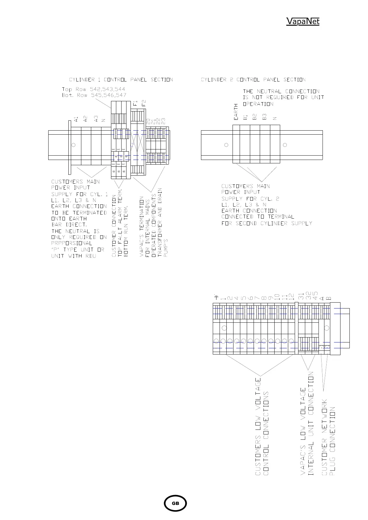
1.4.2 Power Supply Connection
The unit requires the following connections as shown in the
diagram below
1.4.2.1 Volt free alarm outputs
The unit has connections for volt free alarm outputs these are on
the three double terminals next to the main power input terminals.
The top terminals are for unit volt free fault alarm as follows:
542 common for fault alarm
543 Normally closed when no fault
544 Normally open when no fault
The bottom terminals are for unit volt free run signal as follows:
545 Common for run signal
546 Normally closed when unit is in standby or
fault (not running)
547 Normally open when unit is in standby or fault
(not running)
If the unit is part of a master slave system or network, the
run & fault outputs can be selected (via keypad & display)
as either network (system) or unit only. This is selectable at
Service Engineers Level, in the Engineering Menu, in the
window “Fault/Run Scope”. The default is “network”. It is
possible to get both alarm & Run indication in all units:
Single cylinder units will give this indication if the service
interval has expired; Twin Cylinder & Networked units will
give this indication if the service interval has expired or if
the master cylinder is operating and any slave cylinder (or
cylinders) are in fault.
1.4.2.2 Unit control terminals
For unit control and network termination see section
1.6 the terminal layout is shown here.