19
1
2
4
5
6
7
8
9
10
11
12
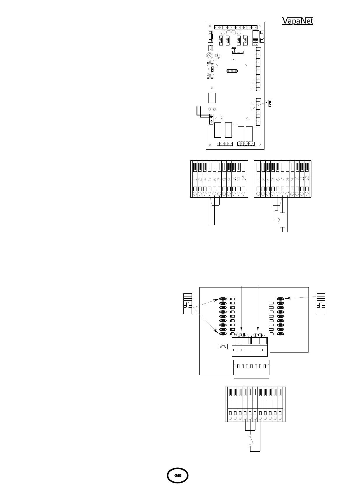
HYGROSTAT WITH VOLT FREE CONTACTS (max.
RESISTANCE OF EXTERNAL CONNECTION 100
Ohms.
1.6 Control Circuit Connections
1.6.1 Control Circuit Wiring
Use a dedicated, earthed metal conduit for both the
control signal cable and the security circuit cables,
sharing the same conduit if practicable.
Use screened cable for all control and security circuit
connections to minimise risk of electrical interference.
The screen should be grounded at the VAPANET end
only. See detail on page 7. NB. The control signal
should be connected to ground at the PCB by
connecting either terminal 5 or 6 to terminal 7 –
I
mportant note if the controller output is
referenced to ground, then the “leg” which is
ground must be the one linked to terminal 7.
1.6.2 Proportional Control
The VAPANET Electrode Boiler (LExxP) models can
all be operated by either a potentiometric signal, a
lonworks network signal or by one of 6 standard
proprietary DC analogue signals.
Input signal:
Potentiometric control
0-5V
0-10V
0-20V
(Actually 0-18V – not phase cut)
2-10V
1-18V
4-20mA
(Ensure jumper J1 is in place)
Network
(Slave unit – demand generated by
Master)
Response:
8-100%
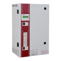
1.6.3 Control Signal Selection
Selection of the control signals is done a part of the
initial set-up procedure using the keypad display. For
confirmation that the signal has been selected, view
the information window. If the unit has not got a
keypad then this is done on the configuration board
1150634 mounted on the main control board 1150630
using the jumpers provided. The top right hand link
should be made indicating that the unit is an
“Electrode boiler” and the appropriate left hand link
representing the actual site control signal should be
linked using the jumper plugs provided
1.6.4 On/Off Control
Vapanet models can be operated by a single
step humidistat which has Volt-free contacts –
select control option Pot.
DC 0 - 20 4 – 20 Ma POTENTIOMETRIC
VOLTAGE CURRENT CONTROL
CONTROL CONTROL min. 135 Ohms
Max. 10,000 Ohms
NOTE :- FOR CURRENT INPUT ONLY JUMPER J1 ON THE
1150630 CONTROL BOARD MUST BE LINKED.
Jumper J1
should be
fitted if
control
signal is
4 – 20 mA
Vapac PART No. 1150630
16
CR6
1
NetCR7
J6
CR5
1
6
6
10
CR3
16
J1
J2
J3
1
F2
CR1
1
F1
CR2
J4
18
CR4
1
16
J5
CR2
configuration
resistor
CSP
CR2
J1
Vapac part no. 1150634
Electro
boiler
Pot high
Pot medium
Pot low
Softened
De-iron
De-min
0-5v
0-10v
2-10v
1-18v
0-20v
4-20mA
pot
Full o/p
or slave
Network
J2
UCP1UCP2