44
33% H
H > 300
H < 300
80 200 min
30 min
25%H
H > 350
50% H
80 min. 200 min.
33% H
H > 375
H > 600
20% H
40% H
40% H
30% H 60% H
H > 400 < 600
250 min.120 min.
200
35 Ø 1 Steam Pipe 35 Ø 1 Steam Pipe 35 Ø 2 Steam Pipes
54 Ø 1 Steam Pipe 54 Ø 2 Steam Pipes 54 Ø 2 Steam Pipes
Fig 2
Fig 4
50% W 50% W
W > 200
W > 200
25% 25%50%
35 Ø or 54 Ø
1 Steam Pipe
2 Steam Pipes
35 Ø or 54 Ø
Fig 3
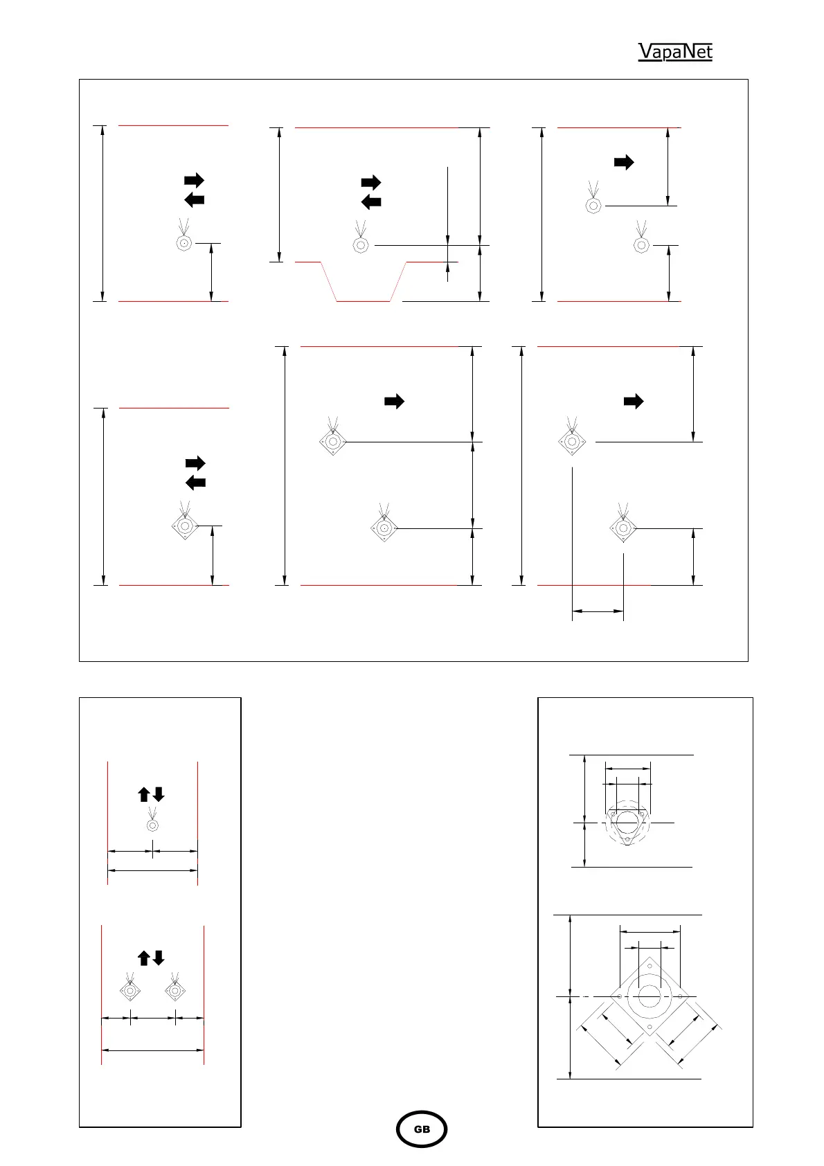
shows the versatility of the steam
pipe / steam hose steam delivery system. It
also indicates where and how condensate
traps / condensate separators should be
used. If the steam pipe slopes such that the
steam connection is lower than the far end of
the pipe, this indicates that a reverse slope
steam pipe is required. This is fitted with a
drain point to allow condensate to be taken
away to a convenient drain.
Figure 2 shows recommendations on how to
space one or more steam pipes in a
horizontal duct.
Figure 3 shows recommendations on how
steam pipes should be spaced in a vertical
duct
Figure 4 shows mounting details for 35 and
54 Ø steam pipes
NB. The duct should be clear of obstructions,
transformations and bends until the steam
has been absorbed into the airflow. A guide
to calculating this distance is available from
Vapac – Part Number 0411047.
October 02
65
80
1
2
0
120
150
150
170 PCD
150
min 80
min 120
min 200
min 250
DUCT MOUNTING DETAIL
For 35 Ø Steam Pipe
For 54 Ø Steam Pipe
DUCT MOUNTING DETAIL
3 x 5.0 Ø
Fixing
holes on
120 PCD.
170 PCD.
holes on
Fixing
4 x 6.4 Ø