EasyManua.ls Logo

VC 7210 - Trigger & Serial (RS232) Interface; Pin Assignments Trigger & Serial (RS232) Interface; Trigger Cable

VC 7210
34 pages
Print Icon
To Next Page IconTo Next Page
To Previous Page IconTo Previous Page
Loading...
VC72XX_HW.pdf Hardware Documentation VC72XX Smart Cameras
1996-2016 Vision Components GmbH Ettlingen, Germany
16
3.2 Trigger & Serial (RS232) Interface
The trigger interface incorporates 2 functions:
1. Image trigger input for hardware controlled image acquisition.
2. Serial RS232 interface.
Multiple use of the trigger interface:
A “Y” adaptor cable is available for connecting several components to the trigger interface refer to
section 3.2.4 for details.
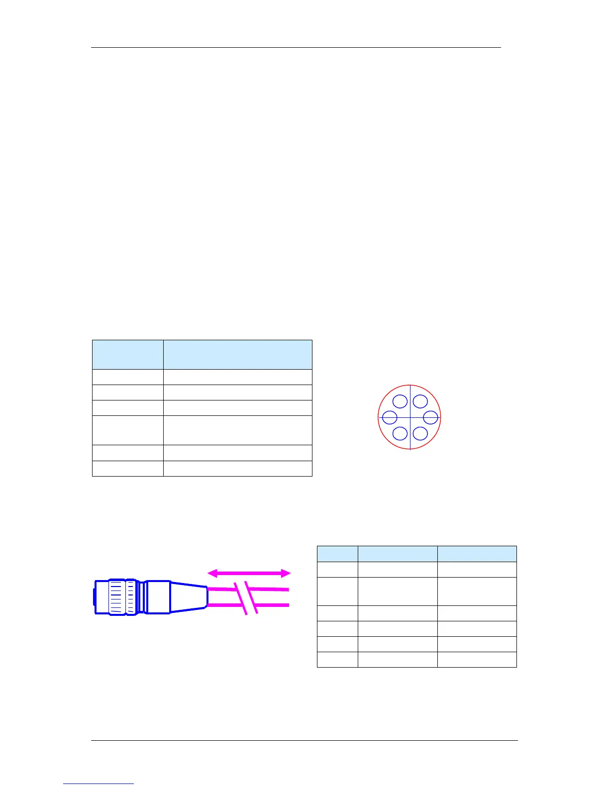
3.2.1 Pin Assignments Trigger & Serial (RS232) Interface
Pin Signals RS232 /
Standard Trigger
rear view camera socket:
1
V24 TxD Out
6
1
2
3
4
5
2
+ 5V (+3.3V*) Out
3
GND
4 V24 RxD In /
Keypad in
5
Trigger Out
6
Trigger In
3.2.2 Trigger Cable
HIROSE 10A-7P-6SC
6-pin. solder plug
Length:
5m
Cable: 0.14mm LiYCY 6 conductors
shielded,
outside diameter 5 mm
2
Pin
Signal
Cable Color
1
V24 TxD Out
green
2 + 5V (+3.3V*)
Out
brown
3
GND
white
4
V24 RxD In
pink
5
Trigger Out
grey
6
Trigger In
yellow
Equipped on one end with a Hirose plug, length 5m, 10m or 25m
Refer to section 4.2 for a list of available cables with order numbers.