VC72XX_HW.pdf – Hardware Documentation VC72XX Smart Cameras
1996-2016 Vision Components GmbH Ettlingen, Germany
3.3.3 Electrical Specifications digital PLC IO Interface
The VC72XX series Smart Camera features digital inputs and outputs that allow for instance direct
input of light barriers signals or the control of pneumatic valves.
Please observe the current and voltage ratings specified in the following sections.
The PLC circuit of all VC Professional and Optimum Smart Cameras is separated from the camera
power supply.
VC72XX
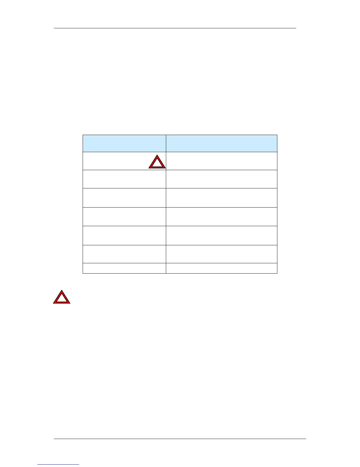
Separation of PLC output
voltage
PLC output supply separated from
camera power supply (common GND)
PLC Input Voltage
12 V– 24 V
PLC Input Current (max)
1.5 mA at 12V to 3.5mA @ 24V
PLC Output Voltage
12 V to 24 V - supplied separately via pin
1 and pin 9.
PLC Output Current (max)
4 x 400 mA
Max total all outputs: 1A
Max Current for 1 Power /
PLC connector pin
500 mA
Power failure detection
-
When using the PLC outputs connect both PLC output supply pins (pin 1 and pin 9) in order to
limit the connector pin current.
The maximum combined current of all outputs should not exceed 1 A.