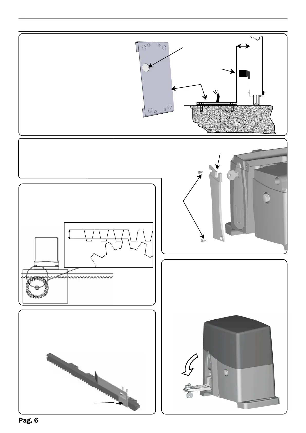
Fasten the rack to the gate firmly,
leaving a distance of between
2 and 3 mm from the motor pinion
(Fig.3).
Fasten the limit stop plates (Cams G)
of the motor on the rack. (Fig. 4)
1. Insert the key provided into the
appropriate cylinder and turn the
key.
2. Pull the lever until it stops
Emergency release
50 mm
cancello
Fig. 1
Fig. 3
2-3mm
Fig. 4
G
Remove the cop cover, unscrew the screws A and
remove the cover B and route the cables into the slot
of the motor. (Fig.2).
A
B
Fig. 2
Fig. 5
Position the plate provided
(Fig. 1) 50 mm from the edge
of the gate and perfectly square
at an angle of 90°.
Before fastening the plate with
cement, dowels or other means,
thread the cable sheath(s)
through the prepared holes.
holes cable
passage
Plate
Gate
Wheel
Rack