75
76
Troubleshooting
Establishing the Arc and Making Weld Beads
Before attempting to weld on a finished piece of work, it is recommended that practice welds
be made on a sample metal of the same material as that of the finished piece.
The easiest welding procedure for the beginner to experiment with MIG welding is the flat
position. The equipment is capable of flat, vertical and overhead positions.
For practicing MIG welding, secure some pieces of 1.6 mm or 5.0 mm (1/16" or 3/16") mild
steel plate 150 mm x 150 mm (6" x 6"). Use 0.9 mm (.035") flux cored gasless wire or a solid
wire with shielding gas.
Setting of the Power Source
Power source and Wirefeeder setting requires some practice by the operator, as the welding
plant has two control settings that have to balance. These are the Wirespeed control (refer
to section 3.06.4) and the welding Voltage Control (refer to section 3.06.10). The welding
current is determined by the Wirespeed control, the current will increase with increased
Wirespeed, resulting in a shorter arc. Less wire speed will reduce the current and lengthen
the arc. Increasing the welding voltage hardly alters the current level, but lengthens the arc.
By decreasing the voltage, a shorter arc is obtained with a little change in current level.
When changing to a different electrode wire diameter, different control settings are required.
A thinner electrode wire needs more Wirespeed to achieve the same current level.
A satisfactory weld cannot be obtained if the Wirespeed and Voltage settings are not adjusted
to suit the electrode
wire diameter and the dimensions of the work piece.
If the Wirespeed is too high for the welding voltage, “stubbing” will occur as the wire dips
into the molten pool and does not melt. Welding in these conditions normally produces a
poor weld due to lack of fusion. If, however, the welding voltage is too high, large drops will
form on the end of the wire, causing spatter. The cor- rect setting of voltage and Wirespeed
can be seen in the shape of the weld deposit and heard by a smooth regular arc sound. Refer
to the Weld Guide located on the inside of the wirefeed compartment door for setup information.
Electrode Wire Size Selection
The choice of Electrode wire size and shielding gas used depends on the following:
Thickness of the metal to be welded
Type of joint
Capacity of the wire feed unit and Power Source
The amount of penetration required
The deposition rate required
The bead profile desired
The position of welding
Cost of the wire
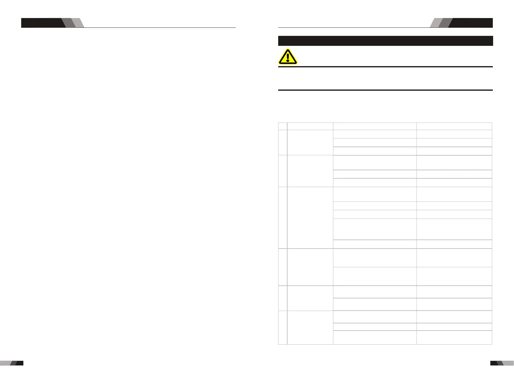
5.1 Troubleshooting
WARNING
There are extremely dangerous voltage and power levels present inside this product. Do
not attempt to open or repair unless you are a qualified electrical tradesperson and you
have hard training in power measurements and troubleshooting techniques.
If major complex subassemblies are faulty, then the Welding Power Source must be returned
to an accredited reseller for repair. The basic level of troubleshooting is that which can be
performed without special equipment or knowledge.
Nr.
1
2
Troubles
Solution
Fan is broken
The power board is broken
There is something in the fan
The start capacitor of fan damaged
Turn on the power
source, power
indicator is lit, fan
is not working.
Turn on the
power source,
fan is working,
power indicator
is not lit
Reasons
Change fan
Clean it
Change capacitor
The power light damaged or
connection is not good
Display panel is broken
Change it
Change it
Change the power light
3
The power cable is broken
Turn on the power
source, fan is not
working ,power
indicator is not lit
The power cable connected not
good
The light of the power indicator is
broken and the problems
mentioned in Nr. 2
Change the light of the power
indicator or refer to the solution
in Nr. 2
Change it
Change it
Repair or change it
Connect correctly
Power on switch is damaged
The power board is broken
4
6
Turn on the power
source, power
indicator is lit, fan
is working, there
is no welding
output.
No no-load
voltage output
(MMA)
Control board is broken
st
1 inverter circuit damaged
If the overheat indicator is on
The main circuit is broken
The machine is broken
Change it
Replace it
Wait a few minutes, the machine
can be operated normal
Check and repair
Consult the dealer or the
manufacturer
5
The number of the
display is not
intact
Digital tube is broken
The display panel is damaged
Change the display panel
Change it
Welding technique
MIG SERIES EQUIPMENT MIG SERIES EQUIPMENT