5
”FIGURE 3.1” on page 4 shows the Mark series ion source’s fundamen-
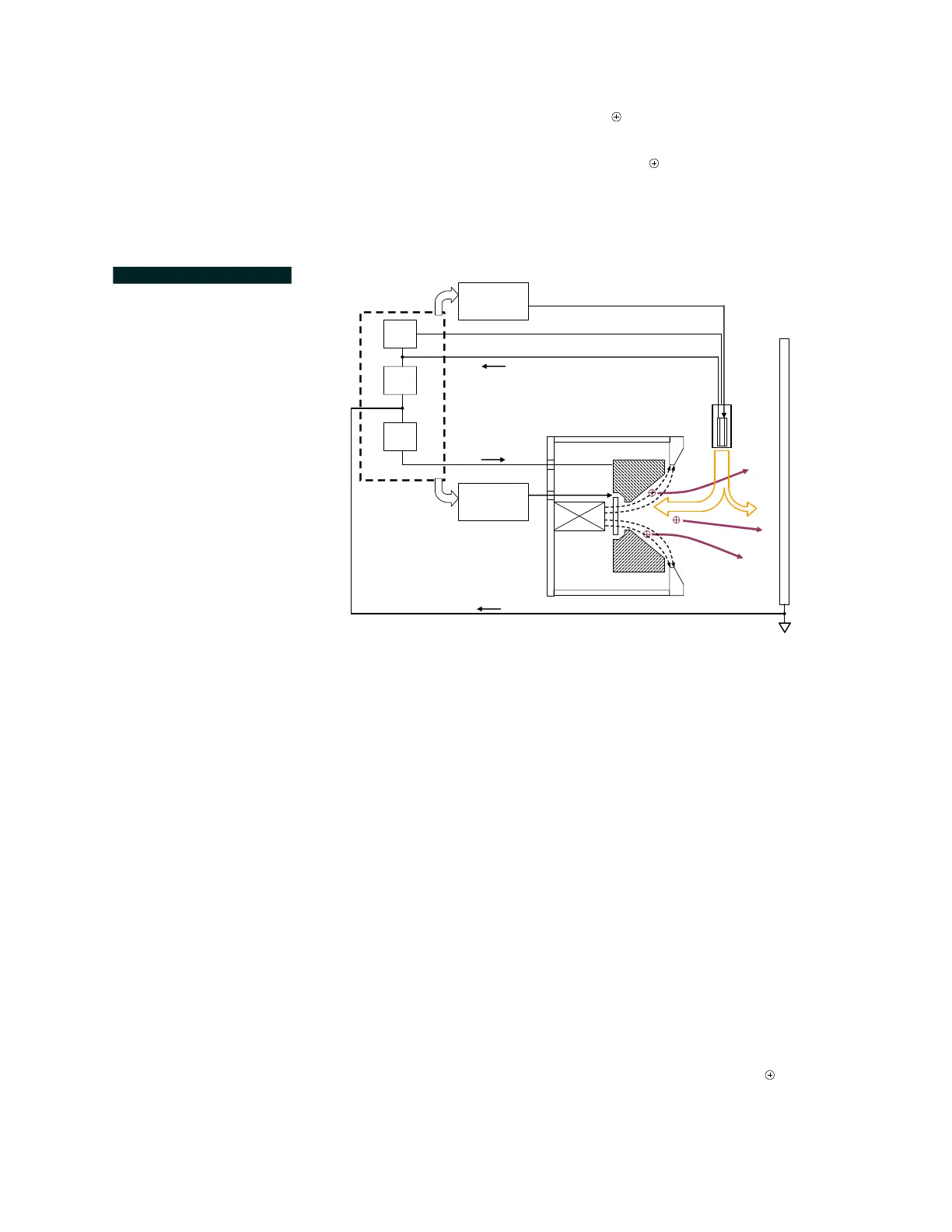
tal operating principles; FIGURE 3.2 illustrates fluid cooled source opera-
tion, together with its HCES, the Veeco Mark series Controller and
both input mass flow controllers (MFC). The ion source and HCES
require separate MFCs. These components are all provided when this
model is ordered as a package.
First, an argon plasma is ignited in the HCES and sustained with current,
I
K,
provided by the controller’s keeper supply. This supply maintains the
HCES’s thermionic emission temperature, to produce the primary elec-
trons. Second, a gas flow is introduced into the source; the unit applies a
voltage-regulated anode potential, V
A
, to drive the ion source discharge
and produce the ion beam. The controller is able to then automatically
regulate the gas flow to the anode, since the electrical impedance of the
plasma between the anode and cathode depends on input gas conditions.
This provides an anode discharge current I
A
, approximating the operator
requested set point as closely as possible.
The power supply uses a third current-regulated emission supply (posi-
tioned between the cathode and the anode supply return) to provide
additional electrons from the HCES to enhance ion beam neutralization.
This emission supply regulates a portion of the cathode return current,
I
E,
most of which is the anode supply return current, I
A
, and any addi-
tional neutralization current, I
N
, returning through the chamber system
ground. By regulating I
E
, the controller allows the operator to inject an
excess electron neutralization current, I
N
. The recommended value for
I
N
is +10 to +20% of the anode current, I
A
. Refer to the Mark series
Controller technical manual for detailed information.
FIGURE 3.2 Ion Source-
HCES-Controller Operation
with MFCs.
I
A
e
-
Anode
Input
Gas
S
S
NS
V
A
+
I
K
+
HCES
(Cathode)
Mark II+
Controller
Source Mass
Flow Controller
(MFC)
I
E
+I
K
I
E
+
I
N
= (I
E
-I
A
)
Ion Source
HCES Mass
Flow Controller
(MFC)
 Loading...