EasyManuals Logo

Veeder-Root TLS-350 PLUS Installation Manual

Veeder-Root TLS-350 PLUS
59 pages
To Next Page IconTo Next Page
To Previous Page IconTo Previous Page
Page #26 background imageLoading...
Page #26 background image
Installation Guide Mag Sump Sensor Installations - Dispenser Pan Sump
21
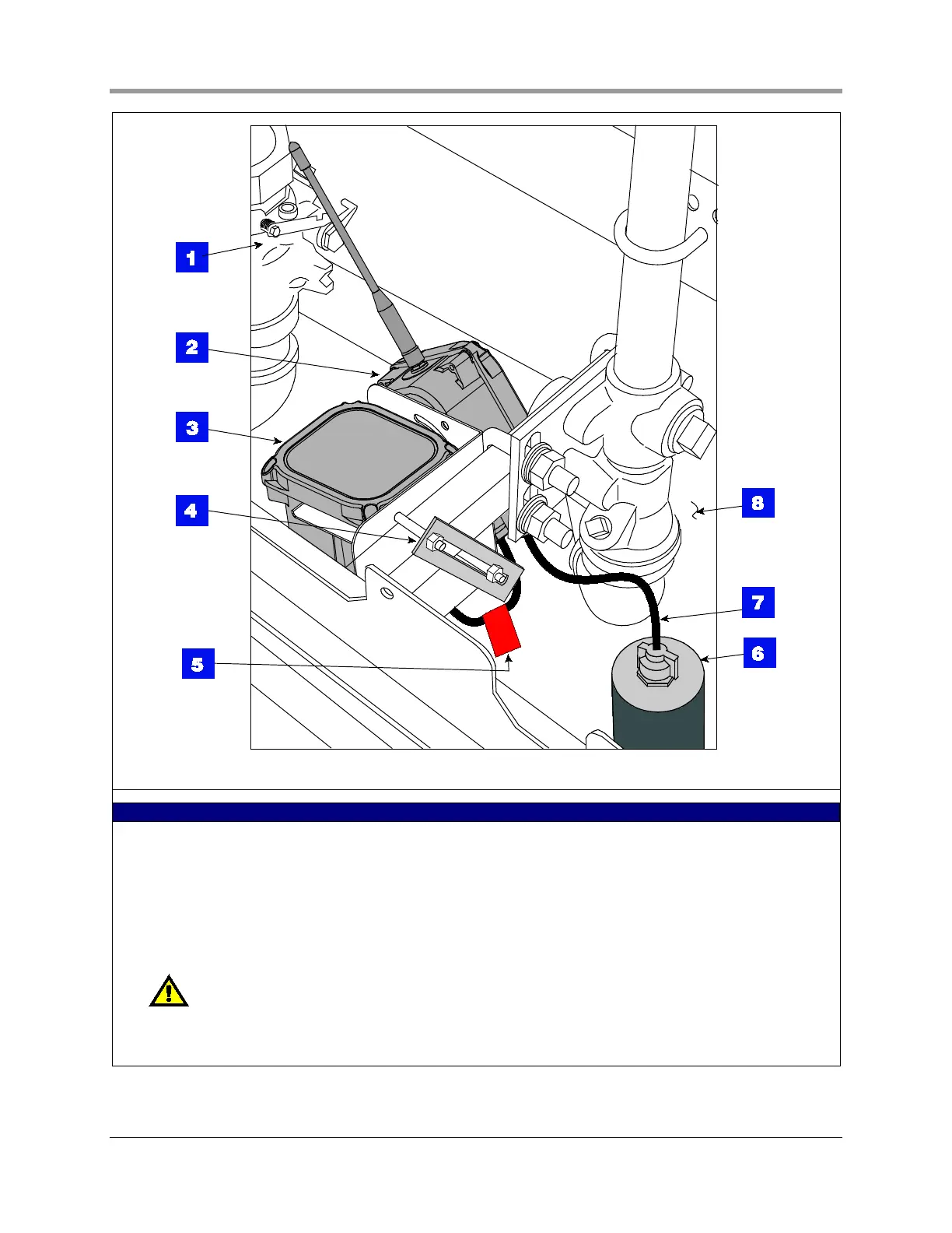
Figure 20. Example transmitter installation in dispenser sump (in operational configuration)
LEGEND FOR NUMBERED BOXES IN FIGURE 20
1. Shear valve
2. Transmitter
3. Battery pack
4. Using 1 x 6 slotted flat bar and two ¼ x 3 bolts from kit, clamp battery support bracket to square tubing support.
5. Battery caution label attached to battery cable (2 places)
6. Dispenser mag sump sensor
7. Sensor cable
NOTE: Intrinsically safe wiring shall be installed in accordance with Article 504-20 of the NEC,
ANSI/NFPA 70.
8. Dispenser sump

Other manuals for Veeder-Root TLS-350 PLUS

Questions and Answers:

Question and Answer IconNeed help?

Do you have a question about the Veeder-Root TLS-350 PLUS and is the answer not in the manual?

Veeder-Root TLS-350 PLUS Specifications

General IconGeneral
CategoryMeasuring Instruments
Number of Tanks SupportedUp to 16
Water DetectionYes
Inventory ManagementYes
Delivery ReportingYes
Alarm ManagementYes
DisplayLCD
EnclosureNEMA 4X
ModelTLS-350 PLUS
ManufacturerVeeder-Root
Temperature MeasurementYes
TypeAutomatic Tank Gauge
Leak DetectionYes
CommunicationRS-232, Ethernet
Product TypeTank Gauging System
ComplianceUL, ATEX

Related product manuals