2 Vac Sensor Installation Vacuum Connections within Containment Sump
2-10
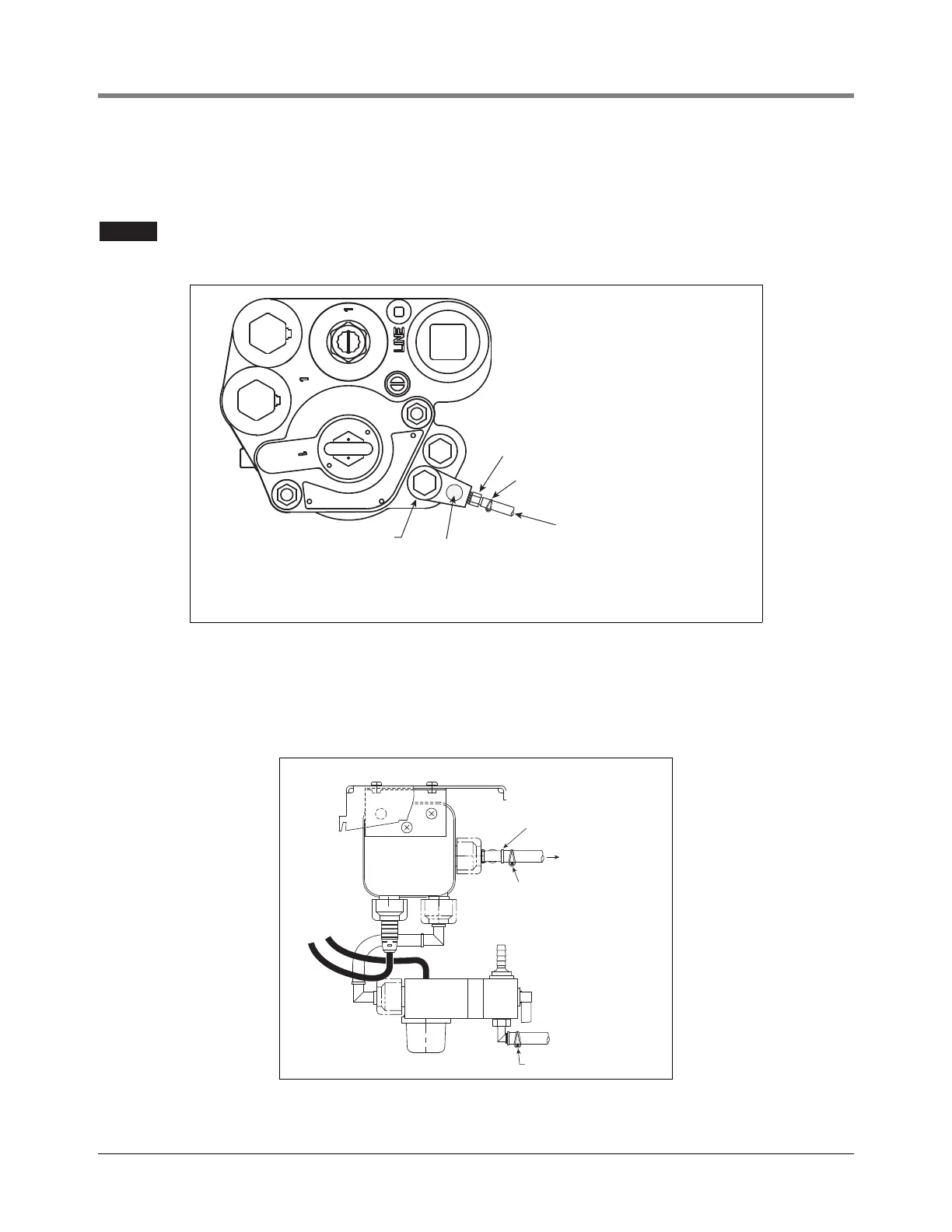
VACUUM CONNECTIONS TO SIPHON PORT OF THE PUMP
1. Figure 2-12 is an example diagram of the vacuum connection at the The Red Jacket STP.
It is recommended that you replace the Siphon Jet assembly on FE Petro pumps used with
the Vac Sensor.
Figure 2-12.- Example Vacuum Source Connection At The Red Jacket STP
2. Measure a length of 1/4” ID tubing to connect 1/4” ID barbed tubing fitting in the siphon cartridge port and the
vacuum input open tee of the Vac Sensor (see Figure 2-13). Plan enough tubing to avoid sharp bends in it or
stretching it. Cut and install this tubing and secure tubing ends with spring clamps.
Figure 2-13.- Connecting Vacuum Tubing From Pump Siphon Port To Vac Sensor
1/4" NPT male to 1/4" barbed adapter
Spring clamp
STP siphon cartridge
1/4"ID tubing connects
to open tee fitting in
Vac Sensor vacuum
manifold
Siphon cartridge
ID mark*
*NOTE: For STP siphon cartridges which have the ID Mark circle,
an external siphon check valve is not required.
1/4 " ID tubing
to STP
Spring clamp
Spring clamp
'STP Siphon' port open tee

 Loading...


