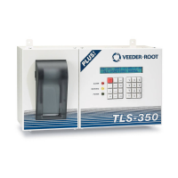
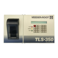
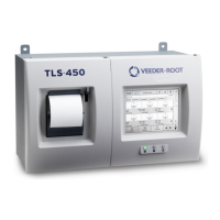
Do you have a question about the Veeder-Root TLS and is the answer not in the manual?
Overview of document scope, installer responsibilities, and site preparation.
Details about Veeder-Root TLS systems, consoles, and magnetostrictive probes.
Explanation of safety symbols and general installation precautions for site personnel.
Grounding, static hazard minimization, and surge protection needs for hazardous areas.
Details on ATEX and IECEx system certifications for intrinsic safety.
Prerequisite steps and considerations before starting the installation process.
Essential conditions for the safe installation of the Mag Probe, including static and material handling.
Procedures for installing probes using wired connections via process connection or riser pipe.
Procedures for installing probes using wireless communication with RF hardware.
Description and components of the Mag Plus Probe Installation kit.
Information about the Cable Seal Kit and its function.
Requirements for surge arrestors conforming to IEC/EN standards and installation guidelines.
Details of the 51mm threaded riser cap assembly and probe leader cable gland.
Details of the 76mm BSP riser cap assembly and probe leader cable gland.
Specific gland assembly for Mag Probe process connections to tank fittings.
Procedures and requirements for installing probes within tank access chambers.
Requirements for providing and installing dedicated probe tapping and riser pipes.
Criteria for installing probes with a 51mm riser pipe, including ID and clearance.
Criteria for installing probes with a 76mm or 102mm riser pipe.
Detailed steps for installing a Mag Probe with a process connection (gland).
Procedure and dimensions required to calculate the correct probe length.
Steps to calculate the minimum access chamber depth using probe length and tank dimensions.
Requirements for riser assemblies using galvanised steel pipe and riser caps.
Instructions for assembling probe sleeves and adapters for risers.
Guidelines for mounting and connecting surge protectors in hazardous locations.
Procedure for connecting probe cables to the TLS console.
Step-by-step instructions for splicing probe field wiring using kits and sealing compound.
Assessment of lightning risk based on site location and conditions.
Assessment of surge risk based on site factors and equipment.
| Brand | Veeder-Root |
|---|---|
| Model | TLS |
| Category | Accessories |
| Language | English |
