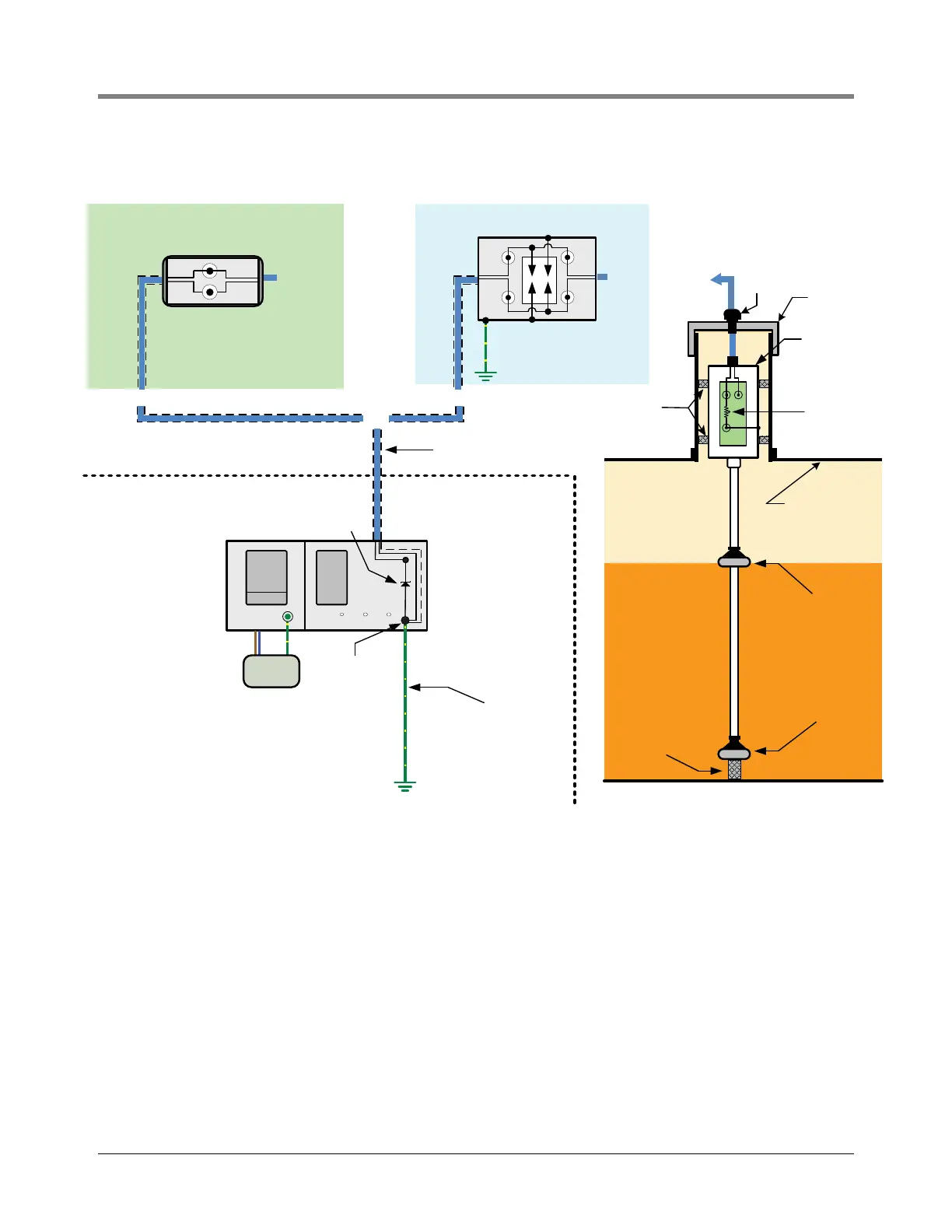
Figure 18. Connection Diagram For A Mag Probe In A Riser Pipe With And Without Optional Surge Protection
ZONE 1 HAZARDOUS LOCATION
Nonhazardous Area
Zone 0
Hazardous
Location
AC
Mains
Equipotential
Bonding Conductor
4 sq.mm
Common
Grounding
System
Probe includes
resistive circuit of
750K to discharge
electrostatic charges.
ATG
Console
Earth
Ground
U
m: 250 V
Intrinsically Safe
Barrier Circuit
Intrinsically Safe
ground
INV.
Tank 1
Tank 2
Tank 3
Shielded Two-Core Cable
for intrinsically safe wiring
Storage Tank
Vapours
Tank Structure
Cable
Bushing
Probe Riser
Pipe with Cap
Magnetostrictive
Probe Enclosure
Sleeves or
adapters
Swimmer
(Liquid product Float)
Swimmer
(Water Float)
Liquid Storage Tank
Storage Tank
Liquid
Probe Boot
(+)
(-)
(+)
(-)
(+)
WHITE
BLACK
Encapsulation Enclosure or
Weatherproof Box
(+)
(-)(-)
(+)
WHITE
Dual Channel Surge Protector
BLACK
To ATG
From
Probe
From
Probe
To ATG
SURGE PROTECTION NOT REQUIRED SURGE PROTECTION REQUIRED
OR
Optional Simple Apparatus
Mount within 1 meter of the
probe riser pipe.
(PA)
(PA)
Note: Each ATG and Magnetostrictive
Probe contains internal surge protection
devices (tranzorbs not shown).