TLS Magnetostrictive Probes International Installation Guide Field Wiring
20
Field Wiring
PROBE TO TLS CONSOLE
Pull appropriate cable from the each probe location to the TLS console.
Explosion could occur if other, non–intrinsically safe wires share TLS intrinsically safe wire conduits or wiring
troughs. Conduits and wiring troughs from probes and sensors to the console must not contain any other wires.
At least 2 metres of free cable must be left for connection at both the TLS console and the probe locations.
Ensure that all cables are correctly identified. All probe field wiring must be legibly and permanently labelled with
the tank number.
Failure to correctly mark probe field wiring may lead to re-work, delays in system installation and additional
charges.
MAXIMUM CABLE LENGTHS
A maximum of 305 metres of cable length per probe must be observed.
SPLICING PROBE FIELD WIRING
1. Insert the probe cable through the top of each riser cap and through the Hummel cable leader bushing.
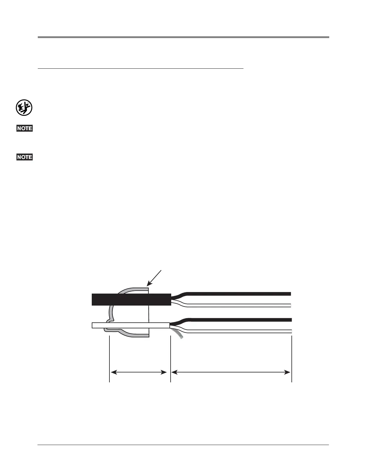
2. Cut the soft vinyl epoxy enclosure end cap entrance holes to accommodate each cable diameter. Keep the
hole sizes to a minimum. Insert about 127mm of each cable through the openings [
Figure 19]. Remove 76mm
of the outer jacket from each cable. Trim the insulation from the conductors.
Figure 19. Splice Length Dimensions
Splice enclosure cap
TLS cable
Probe cable
51mm
Shield wire
76mm
Black
White
White
Black
031-17