TLS Magnetostrictive Probes International Installation Guide Surge Protector
23
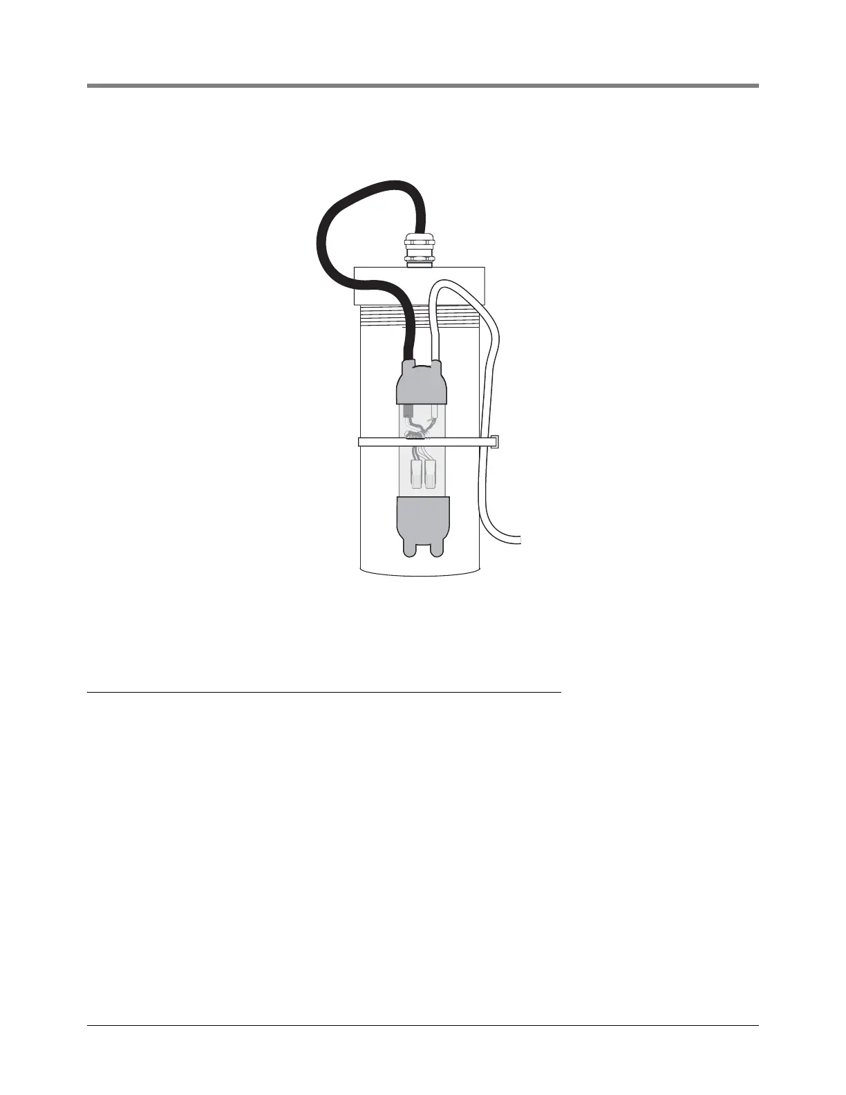
Figure 23. Securing Splice Enclosure With Cable Tie
Surge Protector
INSTALLATION (IF REQUIRED)
When surge protection is required, mount the surge protector as close as possible to the entry point for the probe
leader cable. The surge protector is not polarity sensitive so either cable port may be used for the probe leader
cable. Use the cable port on the opposite side for the wiring coming from the ATG Console. Inside the surge
protector, one side of each spark gap device is wired to the metal enclosure. Use a bonding strap, with a minimum
size of 4 sq. mm, to wire the enclosure to the tank structure using the external potential equalization (PA) terminal.
Connect the wires from each cable as shown in
Figure 24.
031-18