11
Probe Installation
Access Chamber Installation
GENERAL
The installation of the tank access chamber is the responsibility of the customer or their local site contractor and
not that of Gilbarco S.r.l. / Gilbarco UK. However, there are certain requirements which need to be met to allow
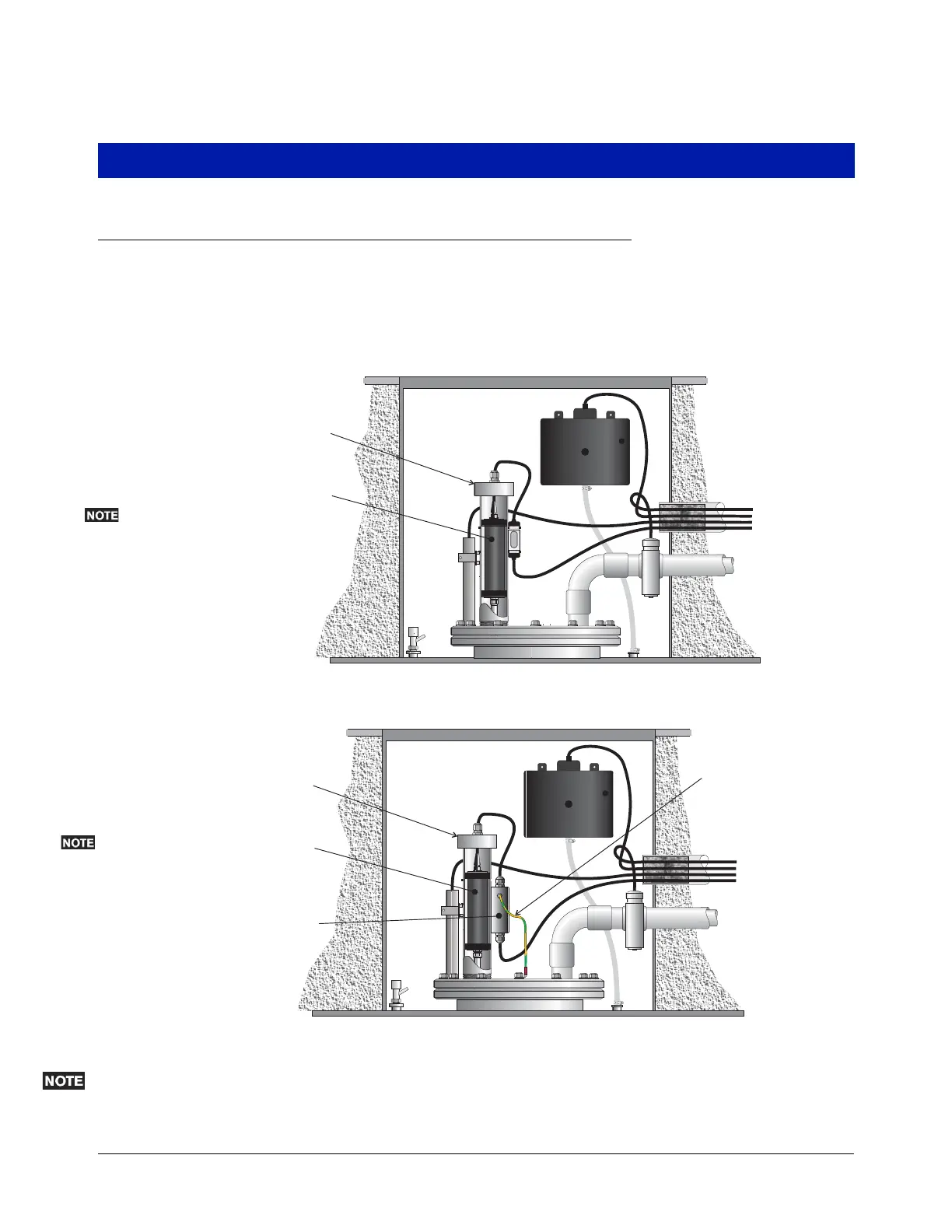
the correct installation of Veeder-Root in–tank monitoring probes. Typical installations are shown in
Figure 10 and
Figure 11.
Figure 10. Typical Tank Lid Access Chamber Installation w/o Surge Protector
Figure 11. Typical Tank Lid Access Chamber Installation w/Surge Protector
To allow adequate space for probe installation and servicing, it is recommended that the access chamber is a
minimum 750mm deep and 600mm wide at the base. See Figure 12.
031-1
Riser Assembly
Magnetostrictive
Probe
Field Cables
to Console
031-22a
Riser Assembly
Magnetostrictive
Probe
Dual Channel
Surge Protector
Field Cables
to Console
Tie Surge Protector (PA)
wire to the tank structure;
e.g., using a customer
supplied terminal lug.
Depending
on probe type,
canister material
may be aluminum
or black conductive
polymer.
Depending
on probe type,
canister material
may be aluminum
or black conductive
polymer.