TLS Magnetostrictive Probes International Installation Guide Access Chamber Installation
12
PROVISION FOR PROBE RISERS
A dedicated probe tapping of either 2-inch BSP (preferred), 3-inch BSP, or 4-inch BSP must be provided.
For maximum height–to–volume accuracy, the probe socket must be as close as possible to the longitudinal axis of
the tank.
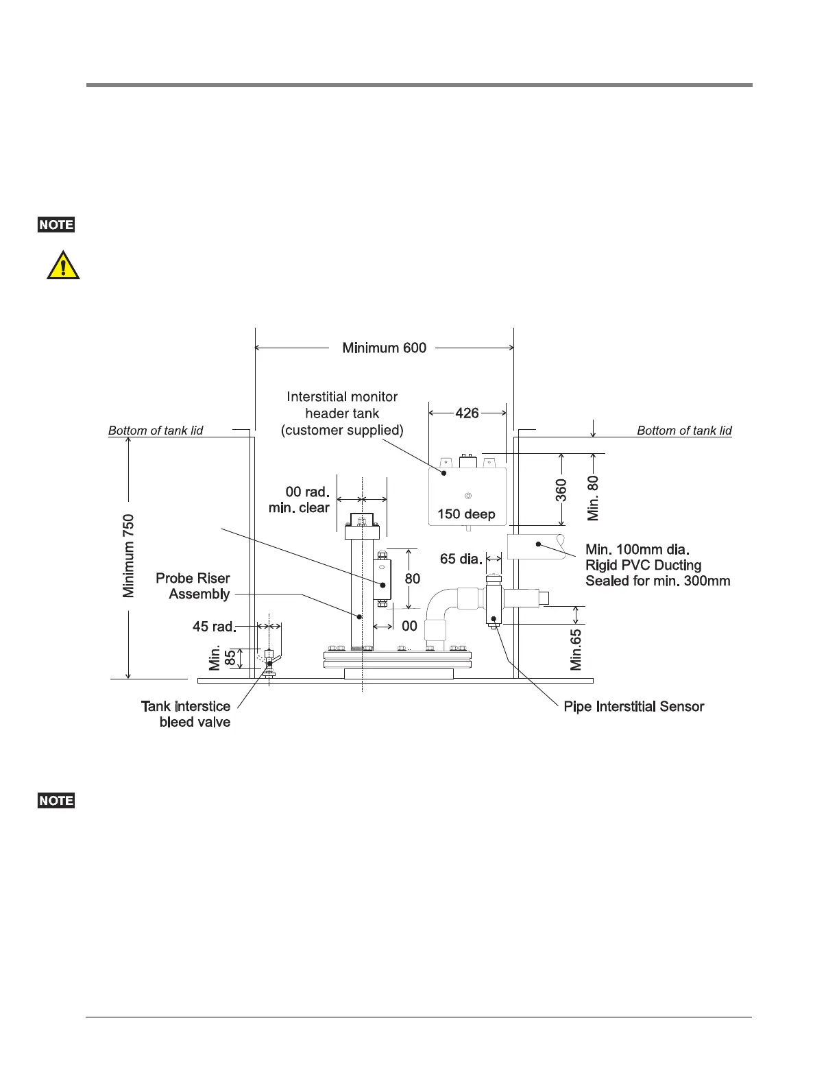
The probe entry must not be obstructed by other pipe work. A free area above the probe socket of at least
100mm radius from its center must be provided. See Figure 12.
WARNING! The probe riser probe riser shall comply with IEC/EN 60079-26 and form a suitable process
connection across the boundary between zone 0 and zone 1 subject to the approval of the local authority.
Figure 12. Tank Lid Access Chamber — Critical Dimensions (in mm)
Where mechanical overfill prevention devices are installed, contractors must ensure that no part of these devices
will be obstructed when the probe and riser assembly are installed.
Failure to comply with this warning may result in the overfill prevention device not operating correctly.
031-5a
1
1
1
Dual Channel
Surge
Protector