TLS Magnetostrictive Probes International Installation Guide Probe and Riser Installation Criteria
15
DETERMINING THE CORRECT PROBE LENGTH
Refer to Figure 15 and carry out the following procedure.
1. Enter dimensions A, B, C, and E in Table 1 .
2. Add dimensions B + C and enter this in column “F”.
3. Select a standard probe length that is equal to or greater than the dimension in column “F”.
Enter the standard probe Length in column “G”.
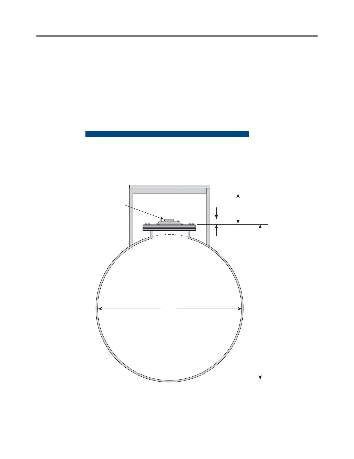
Figure 15. Dimensions Needed To Calculate Custom Probes And Risers
"B"
"E"
"A"
"D"
"C"
A - Tank diameter (internal)
B - Tank bottom to top of tank lid
C - Height of probe entry
D - Probe entry size
E - Vertical clearance for riser assy, above tank lid at probe entry
Dimensions
031-6