TLS Magnetostrictive Probes International Installation Guide Probe and Riser Installation Criteria
14
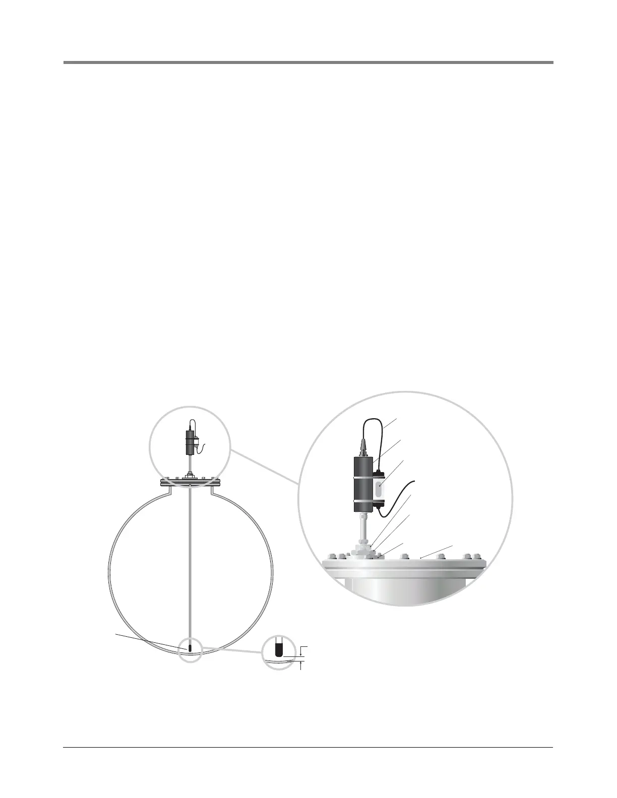
PROBE INSTALLATION USING PROCESS CONNECTION
Certain installations may require a modified probe mounting arrangement consisting of a process connection
(gland) mounted directly to the tank lid as shown in
Figure 14. Either a dedicated tapping or a suitable flange,
tapped G2 inch 11 tpi to DIN 2999 (BS2779) must be provided.
1. Prior to installing or servicing the Magnetostrictive Probe, remove the AC input power going to the TLS
Console and verify that the console power is off. During servicing, disconnect the probe cable and remove the
probe from the tank.
2. Reference Figure 14 to identify the hardware required to complete this installation.
3. Install the flange onto the tank lid then install the gland adapter. For 3-inch and 4-inch float sizes, install the
tube gland and the associated reducer onto the gland adapter prior to performing Step 4.
4. Prior to inserting the Mag Probe, install the tube gland on the probe shaft near the probe canister. Care must
be taken to ensure that the probe shaft is not harmed in any way.
5. Add the fuel float and the water float then install the plastic boot on the very bottom of the probe.
6. Insert the probe assembly into the tank and tighten the tube gland to the gland adapter.
7. Slide the Mag probe downward until the boot makes contact with the tank bottom. Lift the probe at least 10
mm (0.4 inch) from the bottom of the tank to account for thermal expansion of the probe. Tighten the tube
gland once the probe is at the appropriate height.
8. Connect the probe leader cable to the field wiring using the encapsulated splice kit shown in Figure 4.
9. Restore power to the TLS Console and verify that the system is operating properly.
Figure 14. Installation Of A Mag Probe With A Process Connection (Gland)
Probe leader cable
Probe canister
Encapsulated connection
Field cables to console
Flange
Tank lid
10mm (0.4”)
Minimum gap
1-inch BSPto 2-inch BSP reducer
included with 501-000-1207 kit
031-8
Boot
Zone 1 Installation
with Process Connection (Gland)
Process Connection (gland)
adapter P/N 501-000-1206
inlcluded with 501-000-1207 kit