TLS Magnetostrictive Probes International Installation Guide Probe and Riser Installation Criteria
16
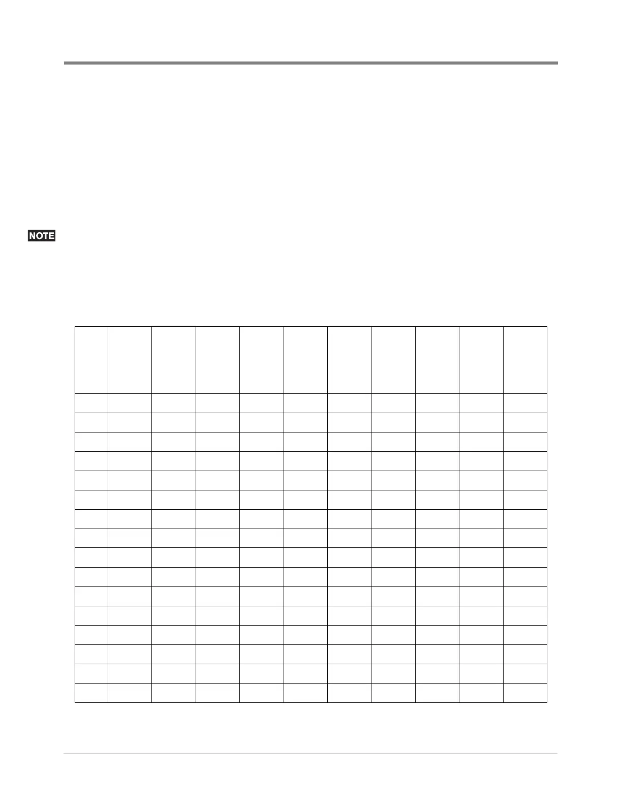
DETERMINING THE MINIMUM ACCESS CHAMBER DEPTH
The minimum access chamber depth, is calculated as follows:
1. To the chosen standard probe Length (“G”), add 290mm, this is the overall probe length; enter this in column
“H”.
2. From the overall probe Length subtract dimension “B + C” (bottom of tank to top of probe flange); the result is
the minimum access chamber depth. Enter in column “I”.
3. Calculate the actual access chamber depth, dimension “E” minus dimension “C” and enter in column “J”
4. Calculate the probe clearance (“J” – “I”) and enter in column “K”.
Column “K” must be zero or a positive number. If the result is a negative number there is insufficient clearance
for the probe and riser assembly. In this case please contact Veeder-Root Technical Support or your local
Representative for details on custom length Mag Probes and special skirted risers, having available the
dimensions A - E shown in
Figure 15.
Table 1. Calculation sheet for determining the correct probe length
TANK
No.
A B C E
F
Bottom of
Tank to Top
of Probe
Entry
“B”+“C”
G
Standard
Probe
Length
H
Overall
Probe
Length
“G”+290mm
I
Minimum
Access
Chamber
Depth
“H”-”F”
J
Actual
Access
Chamber
Depth
“E”-”C”
K
Probe
Clearance
“J”-”I”
1
2
3
4
5
6
7
8
9
10
11
12
13
14
15
16