Replacing the Power Supply (P/N 330020-623) Before Turning Off Power
12
12. Get the new Power Supply board and lower into console.
13. Attach the printer power supply cable to its connector (J1) on the upper right corner of the replacement Power
Supply board.
14. Lineup the two holes in the Power Supply board (see item 4 in Figure 8) with the two retention pins in the
back of the console housing and push the board down until the pins snap into position.
15. Install the three #6 taptite screws (item 1 in Figure 8) and tighten them.
16. Get the AC Input module. Notice that there are two male connectors on the bottom of the AC Input module
board that plug into two female connectors on the Power Supply board. With the handle (item 3 of Figure 7)
of the AC Input module against the left side of the console housing, line up the two AC Input module bottom
connectors over the two female connectors (items 2 and 3 in Figure 8) on the Power Supply board and push
down on the AC Input module until the connectors are firmly seated.
17. Place the Power Supply shield (item 2 in Figure 7) over the Power Supply board and lower it down onto its
two retention pins (see item 2 in Figure 9) and snap it into place.
18. Install the three #8 taptite screws in the AC Input module (see item 1 in Figure 7).
19. Replace the AC Channel cover and install the two #8 taptite screws (see Figure 6).
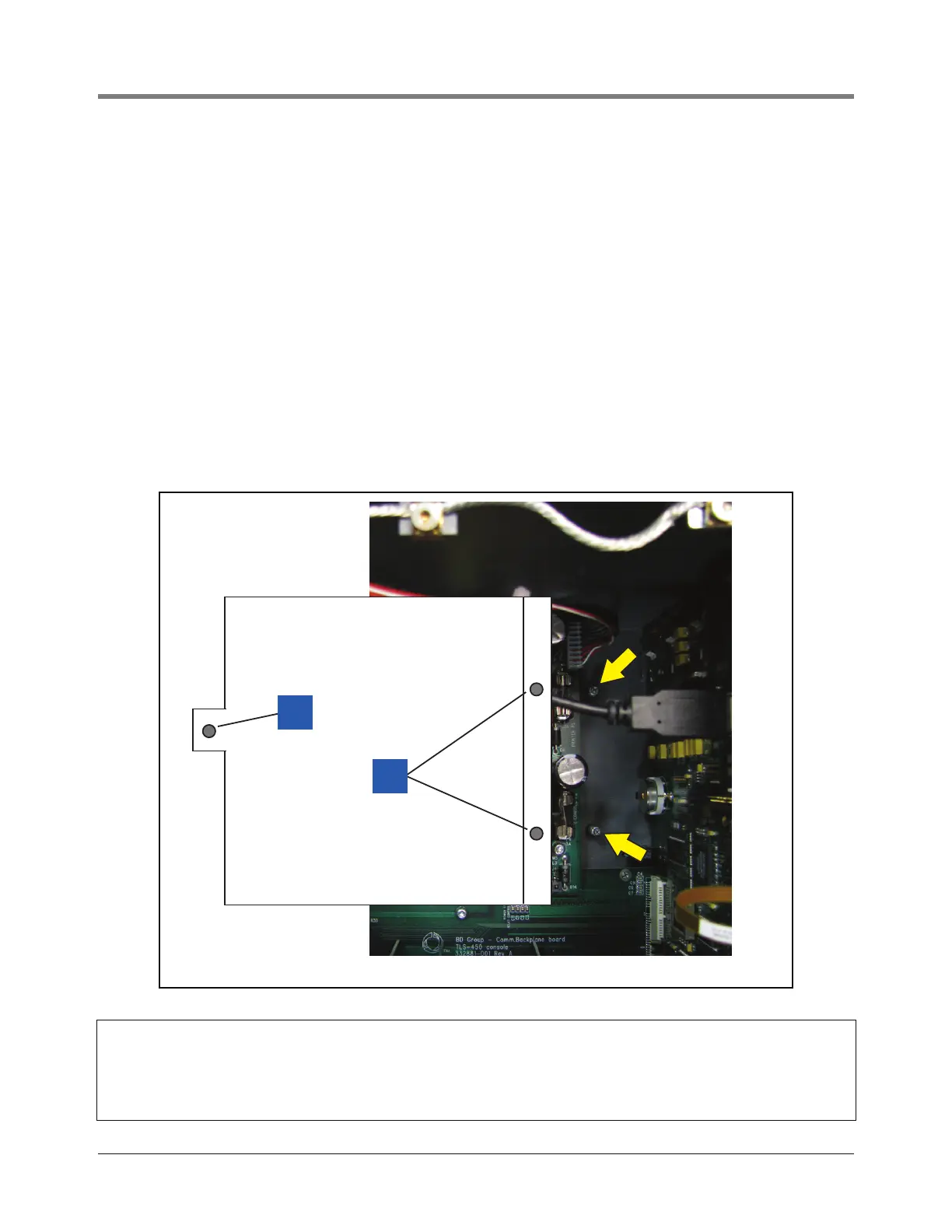
Figure 9. Replacing Power Supply shield over Power Supply board
Legend for numbered boxes in Figure 9
1. This hole lines up over the middle hole in AC Input Module
bracket
2. The two holes in the right side flange of the Power Supply
shield line up over the retention pins (indicated by two arrows)
in the back of the console housing.

 Loading...


