4
Replacing the Display Door Assembly (P/N 330020-625)
1. Switch Off power to the console.
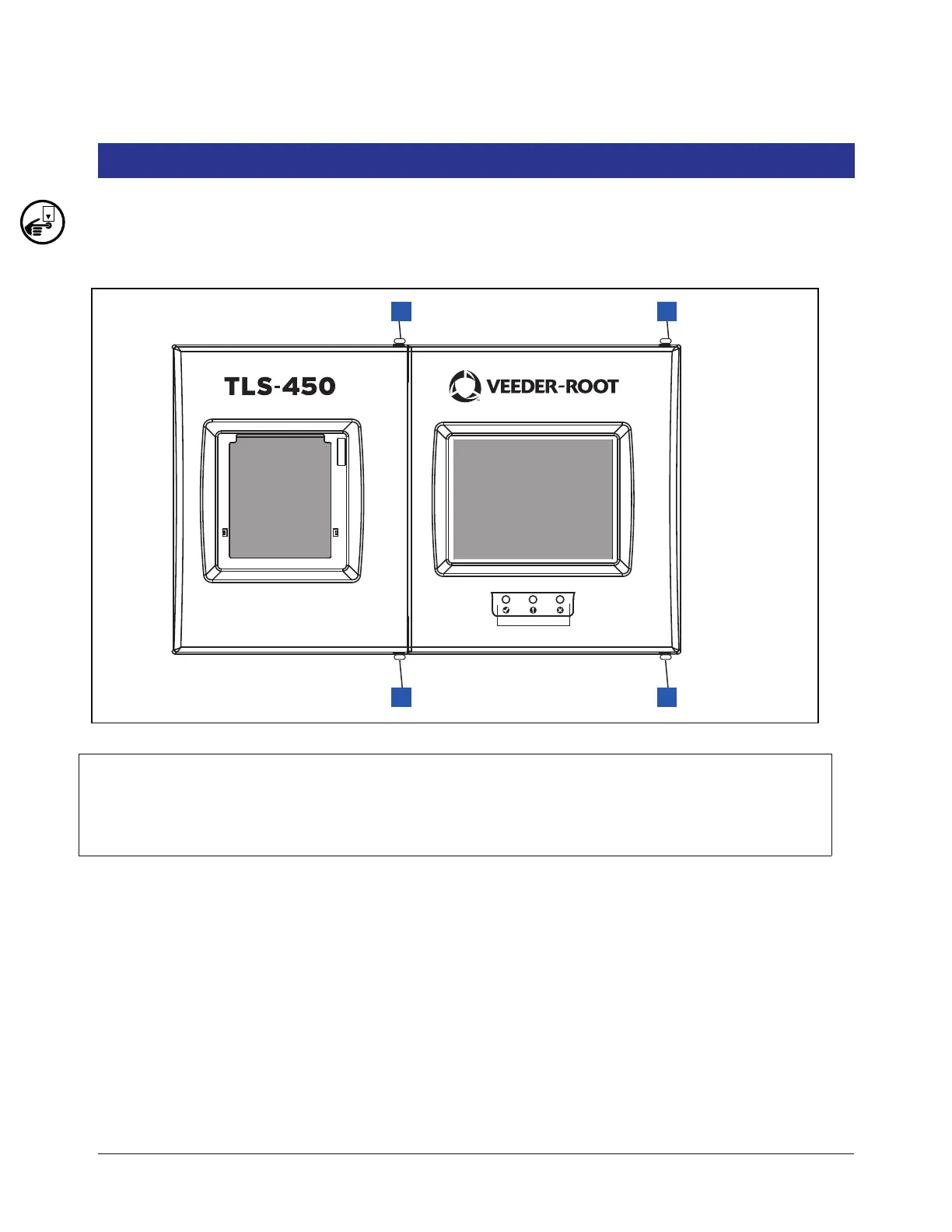
2. Open the two front doors of the console as shown in Figure 2
Figure 2. Front doors
Legend for numbered boxes in Figure 2
3. Disconnect grounding braid from the saddle clamp on the inside of the Display door.
4. Disconnect the three cables from the Display door attached to the CPU board touchscreen connector, the
display data connector and the LED/Display connector (see Figure 3).
5. Remove the top and bottom #8 taptite screws in the Display door hinge and remove the door.
6. Get the replacement Display door and line up the holes in the two door hinges with the top and bottom holes
in the console housing and screw in the top and bottom #8 taptite screws. Tighten the two hinge screws.
7. Reconnect the grounding braid to the saddle clamp on the inside of the Display door.
1. Remove top and bottom #8 taptite screws on right side of left
(Printer) door and swing door to left.
2. Remove top and bottom #8 taptite screws on right side of left
(Display) door and swing door to left.
 Loading...


