Do you have a question about the Vega VEGAFLEX 82 and is the answer not in the manual?
| Brand | Vega |
|---|---|
| Model | VEGAFLEX 82 |
| Category | Accessories |
| Language | English |
Details the manual's function for operation, mounting, and maintenance.
Identifies the intended audience and explains document symbols.
Authorised personnel, appropriate use, and warnings against incorrect operation.
Adherence to regulations, safety instructions, and EU conformity.
Details SIL qualification according to IEC 61508 for safety-instrumented systems.
Details important data on the type label for instrument identification and use.
Explains the TDR sensor's guided microwave pulse technology for level measurement.
Guidelines for proper packaging, transport, and storage conditions to prevent damage.
Instructions on screwing in, protection against moisture, cable glands, and process conditions.
Guidance on optimal installation position and considerations for different vessel types.
Specific instructions for mounting in concrete silos and using mounting sockets.
Notes on welding socket installation and avoiding interference from inflowing medium.
Defines the measuring range reference plane and secure fastening methods.
Safety instructions, voltage supply details, and connection to signal conditioning instruments.
Guidance on cable glands and handling NPT/metric threads for secure sealing.
Recommendations for connecting cable screens and grounding for interference protection.
Illustrates wiring for single and double chamber housings, including Ex versions.
Details on using additional current output and radio modules for extended functionality.
Explains functional safety's role in risk reduction and relevant standards like IEC 61508.
Details characteristics and requirements for instruments in safety-instrumented systems.
Describes safe parameterization tools, verification, and security measures to prevent errors.
Outlines the mandatory sequence for parameter changes and function tests in SIL applications.
Step-by-step guide for inserting and securing the display and adjustment module.
Explanation of display elements, adjustment keys, and key functions.
Detailed parameter configuration for technically demanding measuring points.
Setting distance units, probe length, and application type (liquid/solid, metallic/non-metallic).
Defining upper and lower limits for level measurement and their corresponding distances.
Adjusting damping for signal fluctuations and selecting linearization curves for vessel shapes.
Configuring output characteristics, reaction in case of failure, and min/max current values.
Detecting and marking false signals caused by reflections for accurate level measurement.
Procedure for character string comparison, serial number verification, and locking parameters.
Customizing display language, indication values, and display format.
Accessing device status, peak values for distance, measurement certainty, and electronics temperature.
Simulating output values and analyzing echo curve quality for measurement diagnostics.
Setting date/time, performing resets, and saving parameterization data.
Steps for connecting the PC to the sensor via interface adapter and HART.
Using PACTware and DTMs for sensor parameter adjustment and project configuration.
Recommendation for documenting and saving parameterization data via PACTware.
Using EDD for adjustment programs like AMS™ and PDM.
Parameterizing with Field Communicator 375/475 using EDD and upgrade utility.
No routine maintenance required in normal use; proof testing for SIS is essential.
Information on measured value and event memories for diagnostic purposes.
Categorization and explanation of status messages (Failure, Function check, etc.) with pictographs.
Detailed table of error codes, reasons, and rectification steps for 'Failure' status.
Guides on checking current signals and addressing measurement errors like constant level or filling.
Procedure for replacing the electronics module, including SIL qualified units.
Instructions for shortening or exchanging the probe cable or rod.
Requirements and steps for updating the sensor software, ensuring SIL qualification.
Awareness of process conditions and reverse order steps for safe dismounting.
Guidelines for recycling and avoiding negative environmental effects from disposal.
Comprehensive list of materials, dimensions, weights, and process fittings.
Data on max. tensile load for various cable types, vessel diameters, and cable lengths.
Factors influencing accuracy like temperature drift, interference, gas/pressure effects.
Measuring cycle time, response times, filling speed, ambient, and process conditions.
Details on protection ratings, cable entries, wire cross-sections, and module materials.
Operating voltages, reverse voltage protection, and Bluetooth interface specifications.
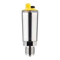
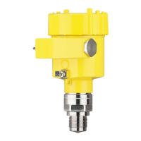
Overview of dimensional drawings and housing types with protection ratings.
Specifications for cable versions with different diameters and PA coating.
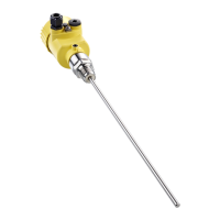
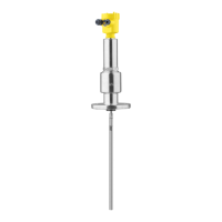
Details for the rod version with Ø 16 mm probe.