620 1 3 54
A
B
C
D
E
2
Blatt +:Von:
Gerät:
SG67_4,4KW_2.1
electronic board SG67
Platine SG67
Blattbeschreibung:
Bearb.:
Gepr.:
Norm:
Erstellt:
Index Datum Geprüft von Prüfvermerk
Blatt:
2
1Blatt -:
23.11.2018
SBAUER
- Projektnr.:
Kunde:
V2.1
620 1 3 54
A
B
C
D
E
P
2
1
-N2
-M1
U1 U2 PE
Pumpe
-Y2
MV-Dampfventil 1
-Y3
MV-Dampfventil 2
-Y4
MV-Befüllung Kessel
-Y5
MV-Befüllung Wassertank
PE321
-X3
Steckdose Bügler 1
PE321
-X4
Steckdose Bügler 2
1 2 PE 1 2 PE1 2 PE
1
2 PE
-K1:A1
- K1:A1
(1.1)
(1.4)
A1
A2
-K2
Heizungsschütz
1 2
(1.2)
3 4
5 6
-S2
1A
1
2A
2
Schalter Bügler 1
-S3
1A
1
2A
2
Schalter Bügler 2
-X2:V
- X2:V
(1.1)
(1.4)
-X2:W
- X2:U
(1.1)
(1.4)
Deckel 1
cover 1
Deckel 2
cover 2
Türe
door
Boden
bottom
Abdeckung
cover
4 bar
Druckschalter
pressure switches
pump
heating contactor
filling valve vessel steam valve 1 steam valve 2filling valve watertank
switch iron 1 switch iron 2
plug socket iron 1
plug socket iron 2
-B2
Wasserstand Kessel
level sensor vessel
-B1
Wasserstand Wassertank
level sensor watertank
bu
bu
bu
gy
bu bu
-W1
bn bu
-W1
bn bu gnye
-W4
bn bu gnye
-W4
bn bu
wh vt
og
wh
bk
bk
bk
vt
gy
- X2:N
-X2:N
(1.4)
(1.1)
bu bu
X1
1
-A1
F3
T 80mA
2 3
F4
T 80mA
F2
T 1A
F1
T 1A
X12 / 8xPE
n. c.
X2
L 2:1
L 4:1
L 4:3
L PS
1 2 3
n. c.
X4
1 2 3 4
L
N
L
N
L
N
L
N
1 2 3
X9
4 1 2 3
X10
4
L 10:1
L 10:2
L 10:3
Signalgeber
sound generator
5V/DC
12V~
GND
GND
Pumpe/pump
Verntile/valves
Spannungsversorgung Primärseite
power supply primary
5 6
L
N
L 4:5
12V~
DI3 (5V/DC)
DI2 (5V/DC)
DI1 (5V/DC)
V2.1
F5
T 250mA
F6
T 250mA
Spannungsversorgung Sekundärseite
power supply secundary
- S1:4
-S1:4
(1.4)
(1.1)
-X2:PE
- X2:PE
(1.1)
(1.5)
gnye
gnye
bn
gnye vt
bk
gnye
og
-W2
bn bu gnye
-W3
bn bu gnye
bn bn
wh
bu bu
gnye
-Z1 -Z2
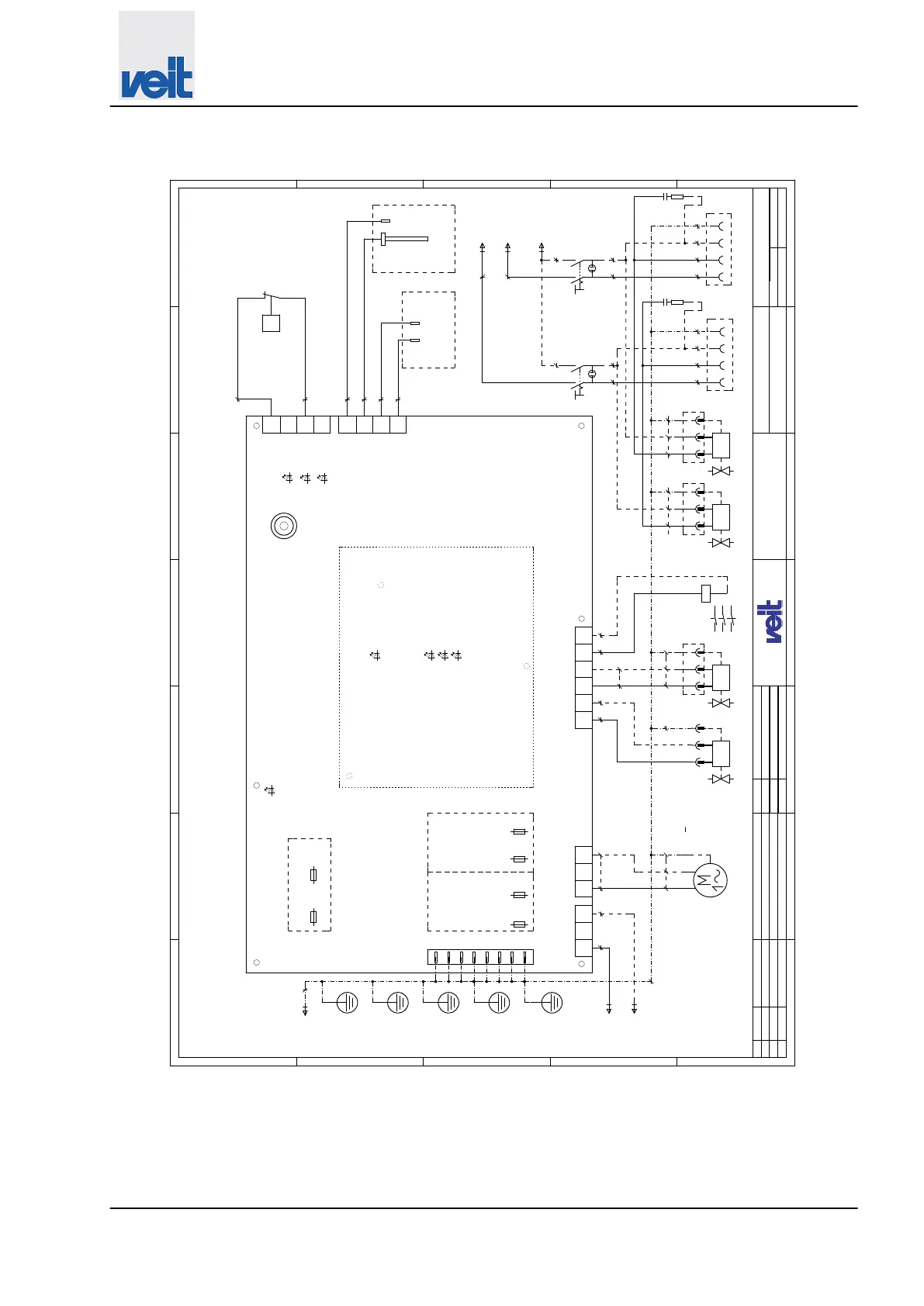
Fig. 39: Circuit diagram_4,4kW_2_1_page 2
Spare parts
Circuit diagram > Circuit diagram 4.4 kW
30.09.2022
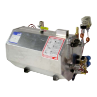
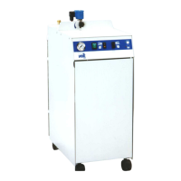
Steam generator VEIT SG67
83